INSTALLATION INSTRUCTIONS
16
6. If an Energy Management System - EMS (load
shed) is to be used with the control, two wires
must be routed to the electrical control box. The
signal required for this function is a normally open
relay contact. When the EMS calls for the com-
pressor to shut off, the relay contacts should
close. Make sure that at least 15" of the EMS
wires extend into the electrical box.
7. In the event that other units are to be installed
(additional zones), an additional 4-conductor com-
munications cable must be routed to the other
locations Make sure that at least 15" of the wire
extends into each of the electrical control boxes.
3.5 SYSTEM CONFIGURATION & CHECK
OUT
Now that the system is installed, it is necessary to config-
ure the electronics, and then check all operations. If the
installation is a single zone, (Without a Furnace) no adjust-
ment to the dip switches are necessary: however, the stage
dip switch is preset to the "ON" position.
3.5.1 ELECTRONIC CONTROL CONFIGURATION
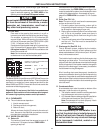
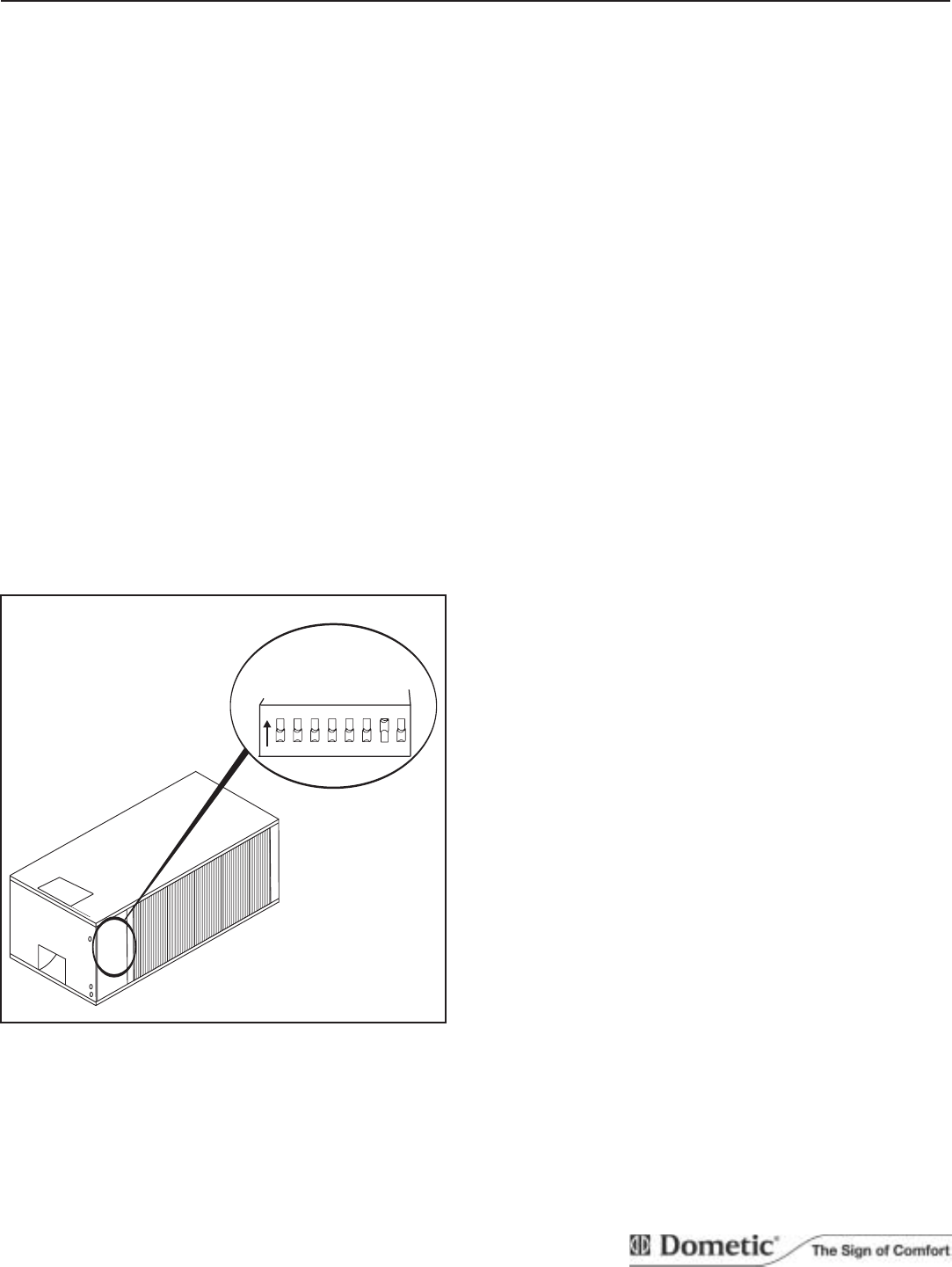
A. If there is more than one zone, the dip switch for
each successive zone must be set to "ON". To gain
access to the dip switches the cover on the unit's
electrical box must be removed.
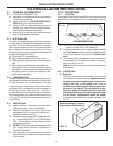
B. Turn "ON" the "ZONE" dip switch on the electronic
control board to set its zone. See figure 3.7.
NOTE: The Control Board should have the Stage Dip
Switch preset to "ON". All other dip switches are
shipped from the factory in the "OFF" position.
C. Turning "ON" of zone 2 dip switch identifies this as
zone 2: likewise zone 3 and 4.
D. Stage dip switch is to be in the "ON" position. This
will control the operation of the second compressor,
provided AC power is available to Circuit #2. The tem-
perature differential between the first and second stage
is preset and cannot be changed.
E. Turn "ON" the furnace dip switch when a furnace is
connected to the blue wires off the control board.
F. Differential dip switch is the difference between the
"ON/OFF" cycle of the thermostat. The normal dif-
ferential is preset in the circuit board with the dip
switchset to the "OFF" positions. In some situations,
it may be necessary to decrease the Differential.
The location of the Comfort Control Center
TM
may
create a condition where the normal differential will
not maintain the temperature at your comfort level. If
this occurs, the Differential can be shortened by plac-
ing the Differential dip switch to the "ON" position.
G. The "GEN START" dip switch - leave in the "OFF"
position.
3.5.2 SYSTEM RESET
On new installation the COMFORT CONTROL CENTER
TM
,
and/or any changes made to the dip switches requires the
electronic control kit to be reset.
A. Turn "ON/OFF" switch to the "OFF" position.
B. Simultaneously depress and hold the "MODE" and
"ZONE" push-buttons while turning the "ON/ OFF"
switch to "ON". The LCD Display should show "FF"
until the "MODE" and "ZONE" push-buttons are re-
leased.
3.5.3 System Checkout
A. Verify that all features of the installed system work.
Check fan speeds, cooling mode, furnace (if con-
nected) and heat pump. If the features do not work,
check all wiring and confirm that the correct options
have been selected on the Electronic Control Box.
3.5.4 Service And Disposal Of Unit
A. The Clean Air Act of 1990 set guidelines in regards
to recapturing or disposition of refrigerants. Service
agents working with reclamation of refrigerants must
be certified by the Environmental Protection Agency
(EPA). Check with the EPA authorities for proper han-
dling or evacuation of refrigerants.
FIG. 3.7
12 345
HEAT STRIP
ZONE 2
ZONE 3
ZONE 4
FURNACE
ON
678
DIFFERENTIAL
STAGE
GEN START


