


7
CAUTION!
MOUNTING
7.4 Electrical Connection
The following electrical connections must be
established on the heat pump:
- Connection of the control wire to the control panel
of the heat pump via terminals X1: L/N/PE.
- Connection of the load wire to the control panel
of the heat pump via terminals X5: L1/L2/L3/PE.
- Connection of the brine pump (to be provided by
the customer) to the control panel of the heat
pump via terminal X1: PE and pump contactor
K2: 2/4/6 (.. 5-17CS), or motor protection F7: 2/4/
6 (.. 21CS).
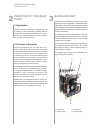
All electrical components required for the operation
of the heat pump are located on the control panel.
For detailed instructions concerning the connection
and functioning of the heat pump controller refer to
the operating manual supplied with the controller.
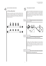
7.3 Connection on Heat Source Side
The following procedure must be observed when
making the connection:
Connect the brine line to the flow and return pipe
of the heat pump.
The supplied strainer must be fitted
in the heat source inlet of the heat pump in order
to protect the evaporator against the ingress
of impurities.
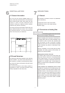
In addition, a powerful vent must be installed at
the highest point of the heat source system. The
hydraulic plumbing diagram must be observed
here.
The brine liquid must be produced prior to
charging the system. The brine concentration
must be at least 25 %. Freeze protection down to
-14°C can thus be ensured.
Only antifreeze products on the basis of mono-
ethylene glycol or propylene glycol may be used.
The heat source system must be vented (de-
aerated) and be checked for leaks.
The brine solution must contain at
least 25 % of an antifreeze and corrosion
protection agent on a monoethylene glycol or
propylene glycol basis.
CAUTION!
An all-pole disconnecting device with a contact gap
of at least 3 mm (e.g. utility company disable contac-
tor or power contactor) as well as a 3-pole circuit
breaker with simultaneous tripping of all external
conductors must be provided . The required cross-
sectional area of the conductor is to be selected
according to the power consumption of the heat
pump, the technical connection requirements of the
relevant utility company and all applicable regula-
tions. Power consumption data of the heat pump is
provided in the product literature and on the
nameplate. The terminals are designed for a max.
conductor cross-section of 10 mm˝.
The clockwise phase sequence
must be observed when connecting the load line
(the heat pump will deliver no output and will be
very noisy when the phase sequence is in-
correct).
CAUTION!