


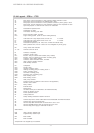
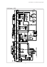
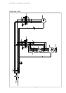
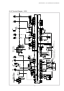
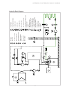


36
12.4.8 Legend .. 21CS
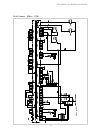
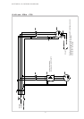
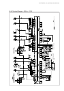
APPENDIX: 12.4 WIRING DIAGRAMS
A1 Wire jumper, must be removed if a utility company disable contactor is used
A2 Wire jumper, must be removed if 2nd disable input is used
B2* Pressostat low pressure, brine
B3* Thermostat, hot water
B4* Thermostat, swimming pool water
E9* Electr. immersion heater, hot water
E10* Suppl. heating system (boiler or electr. heating element)
F2 Load fuse for N1 relay outputs across J12 and J13 4.0 A slow
F3 Load fuse for N1 relay outputs across J15 to J18 4.0 A slow
F4 Pressostat high pressure
F5 Pressostat low pressure limiter with manual reset
F12 Thermostat N7
F14 Electronic motor protection, compressor 1
H5* Lamp, remote fault indicator
J1...J18 Terminal connector at N1
K1 Contactor, compressor
K5 Contactor, primary pump
K1.1 Contactor, starting current limiter
K1.2 Time-delay relay for delay of K1
K11* Electron. relay, remote fault indicator (relay module)
K12* Electron. relay, swimming pool circulating pump (relay module)
K20* Contactor, suppl. heating system (boiler or electr. heating element)
K21* Contactor, electr. immersion heater for hot water
K22* Utility company disable contactor
K23* SPR auxiliary contactor
M1 Compressor
M11* Primary pump
M13* Heating circulating pump
M15* Heating circulating pump heating circuit 2
M16* Suppl. circulating pump
M18* Hot water circulating pump
M19* Swimming pool water circulating pump
M21* Mixer main circuit
M22* Mixer heating circuit 2
N1 Heat pump controller
N7 Soft start board
N10* Remote control station
N11* Relay module
Q1 Power protection switch, brine pump
Q2 Power protection switch, compressor
R1 External sensor
R2 Return sensor
R3 Hot water sensor (as an alternative to hot water thermostat)
R5 Sensor for heating circuit 2
R6 Freeze protection sensor
R7 Coding resistor 8k
T1 Safety isolating transformer 230/24V AC-28V A
X1 Terminal strip mains control L/N/PE-230V AC-50 Hz/fuses/N and PE-terminal block
X2 Terminal strip 24V AC terminal block
X3 Terminal strip GND terminal block for sensors R1/-2 and -3 at J2
X4 Terminal strip GND terminal block for sensors R5 and -6 at J6
X5 Terminal strip power supply 3 L/PE-400V AC-50 Hz
Abbreviations:
EVS Utility company disable input
SPR Supplementary disable input
MA Mixer OPEN
MZ Mixer CLOSED
* Components to be supplied by the customer