


14
APPENDIX: 12.2 EQUIPMENT DATA
Equipment Data
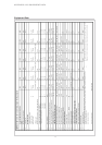
EQUIPMENT DATA for brine-to-water heat pumps for heating purposes
1
TYPE AND COMMERCIAL DESCRIPTION ..5CS ..7CS ..9CS ..11CS ..14CS ..17CS ..21CS
2
MODEL
2.1 Enclosure type acc. to EN 60 529 IP 20 IP 20 IP 20 IP 20 IP 20 IP 20 IP 20
2.2 Installation site indoors indoors indoors indoors indoors indoors indoors
3
PERFORMANCE DATA
3.1 Operating temperature limits:
Heating water supply °C max. 55 max. 55 max. 55 max. 55 max. 55 max. 55 max. 55
Brine (heat source) °C -5 to +25 -5 to +25 -5 to +25 -5 to +25 -5 to +25 -5 to +25 -5 to +25
Antifreeze agent
monoethylene glycol monoethylene glycol monoethylene glycol monoethylene glycol monoethylene glycol
Minimum brine concentration (-13°C freezing temperature)
0,25 0,25 0,25 0,25 0,25 0,25 0,25
3.2 Heating water temperature spread at B0 / W35
K 10,1 9,9 10,5 10,1 9,6 9,3 11,3
3.3 Heating capacity / coeff.of perform. at B-5 / W55
1)
kW / --- 3,8 / 1,96 5,6 / 2,2 7,7 / 2,3 9,4 / 2,4 12,5 / 2,6 14,4 / 2,6 17,9 / 2,5
at B0 / W50
1)
kW / --- 4,8 / 2,75 6,7 / 2,9 9,0 / 3,1 11,3 / 3,0 14,2 / 3,4 16,7 / 3,2 20,4 / 3,1
at B0 / W35
1)
kW / --- 5,3 / 4,3 6,9 / 4,3 9,2 / 4,4 11,8 / 4,4 14,5 / 4,5 17,1 / 4,6 21,1 / 4,3
3.4 Sound power level dB(A) 54 55 56 56 56 58 59
3.5 m³/h / Pa 0,45 / 2000 0,6 / 2500 0,75 / 4500 1,0 / 3500 1,3 / 3500 1,5 / 4000 1,6 / 6000
3.6 Brine flow rate at internal pressure difference (heat source) m³/h / Pa 1,2 / 6500 1,7 / 10000 2,3 / 16000 3,0 / 13000 3,5 / 13000 3,8 / 9000 6,0 / 12000
3.7 Refrigerant; total charge weight Type / kg R407C / 1,7 R407C / 1,5 R407C / 1,8 R407C / 2,0 R407C / 2,3 R407C / 2,8 R407C / 4,5
4
DIMENSIONS; CONNECTIONS AND WEIGHT
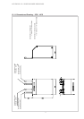
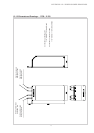
4.1 Equipment dimensions without connections
4)
H x W x L mm
800 × 600 × 500 800 × 600 × 500 800 × 600 × 500 800 × 600 × 500 800 × 600 × 500 1380 × 600 × 500 1380 × 600 × 500
4.2 Equipment connections for heating system inches thread 1" i/ext. thread 1" i/ext. thread 1" i/ext. thread 1" i/ext. thread 1" i/ext.
4.3 Equipment connections for heat source inches thread 1¼" i/ext. thread 1¼" i/ext. thread 1¼" i/ext. thread 1¼" i/ext. thread 1¼" i/ext. thread 1½" i/ext.
4.4 Weight of transport unit(s) incl. packaging kg 131 133 134 145 157 165 215
5
ELECTRICAL CONNECTION
5.1 Nominal voltage; fusing V / A 400 / 16 400 / 16 400 / 16 400 / 16 400 / 16 400 / 16 400 / 20
5.2 Nominal power consumption
1)
B0 W35 kW 1,23 1,6 2,07 2,66 3,22 3,72 4,91
5.3 Starting current with soft starter A 22 (w/out soft st.) 30 (w/out soft st.) 15 26 26 27 29
5.4
Nominal current B0 W35 / cosϕ
A / --- 2,22 2,89 3,77 4,84 5,81 6,35 8,86
6
COMPLIES WITH EUROPEAN SAFETY REGULATIONS
3) 3) 3) 3) 3) 3) 3)
7
OTHER DESIGN CHARACTERISTICS
7.1 Water inside equipment protected against freezing
2)
ja yes yes yes yes yes yes
7.2 Performance settings 1 1 1 1 1 1 1
7.3 Controller internal / external internal internal internal internal internal internal internal
1) 2)
4)
3) See EC Declaration of Conformity
Subject to technical modifications
Issued 24.03.2004
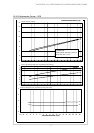
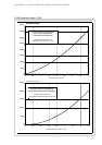
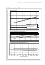
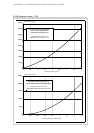
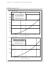
These data characterize the size and performance capability of the system. For economic and energetic reasons, additional factors such as balance
point and control need to be takeninto consideration. Abbreviations have the following meaning, e.g. B10 / W55: heat sourcetemperature 10 °C and
heating water supply temperature 55 °C.
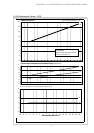
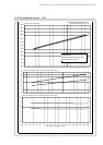
Heating water flow rate at internal pressure difference
The heating circulating pump and the controller of the heat pump must be ready for operation at all times.
Please keep in mind that morer space is required for pipe connection, operation and maintenance.