


32
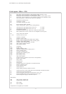
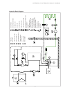
12.4.4 Legend .. 5CS to .. 17CS
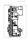
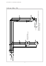
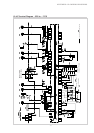
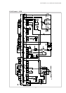
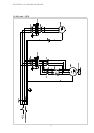
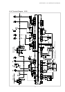
APPENDIX: 12.4 WIRING DIAGRAMS
A1 Wire jumper, must be removed if a utility company disable contactor is used
A2 Wire jumper, must be removed if 2nd disable input is used
A3 Wire jumper, must be removed if a motor protection contact for primary pump is used
A4 Wire jumper, must be removed if a motor protection contact for the compressor is used
Open wire jumpers or contacts mean: lock-out or malfunction
B2* Pressostat low pressure, brine
B3* Thermostat, hot water
B4* Thermostat, swimming pool water
E9* Electr. immersion heater, hot water
E10* Suppl. heating system (boiler or electr. heating element)
F2 Load fuse for N1 relay outputs across J12 and J13 4.0 A slow
F3 Load fuse for N1 relay outputs across J15 to J18 4.0 A slow
F4 Pressostat high pressure
F5 Pressostat low pressure (in SI 17CS, F5 is a limiter with manual reset)
F15* Motor protection M11, from SI 9CS to SI 17CS integrated in primary pump
H5* Lamp, remote fault indicator
J1...J18 Terminal connector at N1
K1 Contactor, compressor
K5 Contactor, primary pump
K11* Electron. relay for remote fault indicator (relay module)
K12* Electron. relay for swimming pool water circulating pump
K20* Contactor, suppl. heating system
K21* Contactor, electr. immersion heater, hot water
K22* Utility company disable contactor
K23* SPR auxiliary contactor
M1 Compressor
M11* Primary pump
M13* Heating circulating pump
M15* Heating circulating pump for heating circuit 2
M16* Suppl. circulating pump
M18* Hot water circulating pump
M19* Swimming pool circulating pump
M21* Mixer heating circuit 1
M22* Mixer heating circuit 2
N1 Heat pump controller
N7 Soft start control (not fitted in SI 5CS and SI 7CS appliances)
N10* Remote control station
N11* Relay module
R1 External sensor
R2 Return sensor
R3 Hot water sensor (as an alternative to hot water thermostat)
R5 Sensor for heating circuit 2
R6 Freeze protection sensor
R7 Coding resistor 8k
T1 Safety isolating transformer 230/24V AC-28V A
X1 Terminal strip mains control L/N/PE-230V AC-50 Hz/fuses/N and PE-terminal block
X2 Terminal strip 24V AC-terminal block
X3 Terminal strip GND terminal block for sensors R1/-2 and -3 at J2
X4 Terminal stripGND terminal blocl for sensors R5 and -6 at J6
X5 Terminal strip power supply 3 L/PE-400V AC-50 Hz
Abbreviations:
EVS Utility company disable input
SPR Supplementary disable input
MA* Mixer OPEN
MZ Mixer CLOSED
*Components to be supplied by the customer