


www.dimplex.de E-6
English
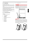
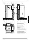
6.4
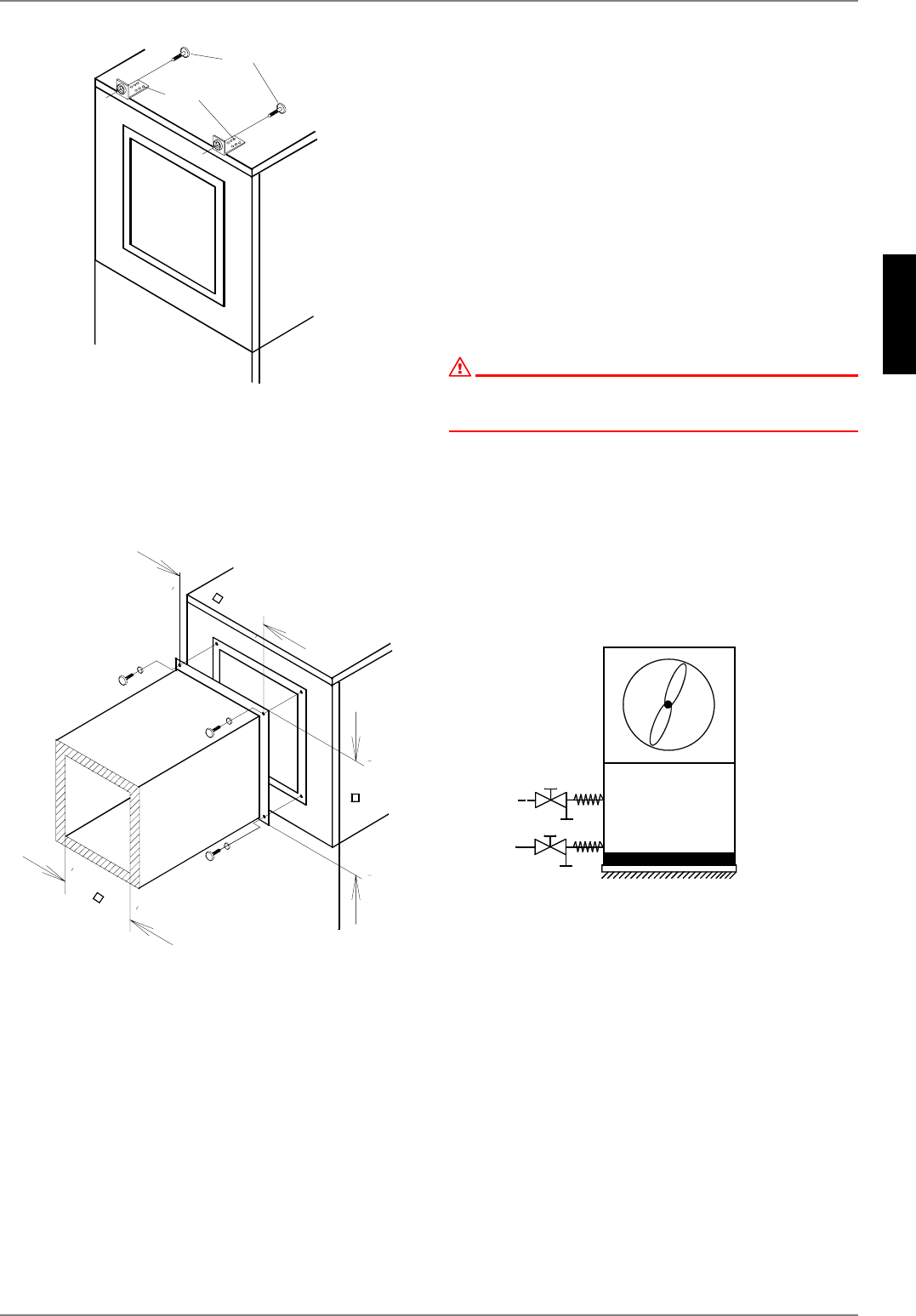
The air outlet can be optionally mounted directly to a wall open-
ing or to a longer duct (available as an accessory). Use the same
mounting procedure as for the air inlet.
If a flange-mounted air duct is used on the air outlet side, it is se-
cured with 4 M8 x 16 hexagon bolts in the threaded holes pro-
vided. When doing this, ensure that the air duct stubs only touch
the insulation. There should be no contact with the external
sheeting.
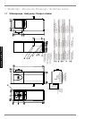
Observe the external and internal dimensions as specified in the
figure. Also ensure that the vibration and duct isolation are ade-
quate.
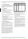
6.3 Heating System Connection
To enable connection to the heating system, flexible hose con-
nection pieces and double nipples with a 1" external thread are
included with the heat pump. These allow the optional use of a
threaded or flat gasket connection to the heating system.
If the heat pump is not intended to be used to heat up the hot wa-
ter, the hot water output must be permanently sealed using the
supplied sealing plug.
Before connecting the heating water system to the heat pump,
the heating system must be flushed to remove any impurities,
residue from sealants, etc. Any accumulation of deposits in the
liquifier could cause the heat pump to completely break down.
An overflow valve is installed in the device for systems in which
the heating water flow can be shut off via the radiator or thermo-
stat valves. This ensures a minimum heating water flow rate
through the heat pump and helps to avoid faults.
Once the heating system has been installed, it must be filled, de-
aerated and pressure-tested.
The integrated expansion vessel has a volume of 24 litres. This
volume is suitable for buildings with a living space area to be
heated of maximum 200 m².
The volume should be checked by the heating system engineer.
If necessary, an additional expansion vessel must be installed
(according to DIN 4751, Part 1). The tables listed in the manufac-
turers' catalogues simplify dimensioning the system on the basis
of the water content. Allow for a buffer tank volume of 80 litres
when making the calculation.
ATTENTION!
In the case of large-volume heating circuits, an additional expansion
vessel must be used to supplement the installed expansion vessel (24
litres, 1.0 bar admission pressure).
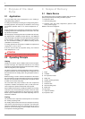
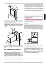
Antifreeze
A method of manual drainage (see illustration) should be pro-
vided for heat pumps which are exposed to frost. The antifreeze
function of the heat pump controller is active whenever the con-
troller and the heat circulating pumps are ready for operation. If
the heat pump is taken out of service or in the event of a power
failure, the system has to be drained. The heating circuit should
be operated with a suitable antifreeze if heat pump systems are
implemented in buildings where a power failure can not be de-
tected (holiday home).
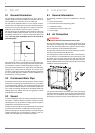
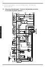
6.4 Electrical Connection
The power supply and control voltage are supplied using stand-
ard cables (load: 3-core, control: 3-core).
A disconnecting device with a contact gap of at least 3 mm (e.g.
utility blocking contactor or power contactor) as well as a 1-pole
circuit breaker must be installed in the power supply by the cus-
tomer (tripping current in compliance with the Device Informa-
tion).
The control voltage must be protected by a 10 A fuse. See Ap-
pendix Circuit Diagrams for detailed information.
[
0[
P
L
Q
0[
P
D
[