


E-5
English
5
5Set-UP
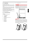
5.1 General Information
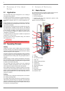
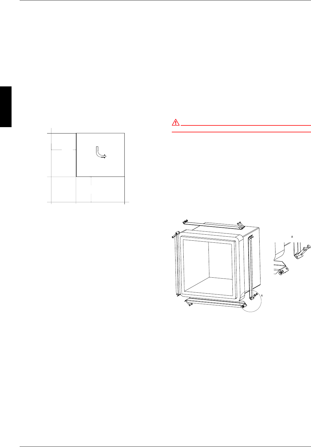
The heat pump is designed for installation in a corner. Other in-
stallation locations are also possible in combination with an air
duct (available as an accessory) on the air outlet side.
The unit must be installed indoors on a level, smooth and hori-
zontal surface. The entire base of the frame should lie directly on
the floor to ensure a good soundproof seal. If this is not the case,
additional sound insulation measures may be necessary.
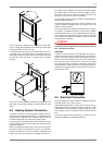
The heat pump must be installed so that maintenance work can
be carried out without being hindered. This can be ensured by
maintaining a clearance of 1 m in front and to the left of the heat
pump. The side panel assemblies must not be covered by
connecting pipes.
Never install the device in rooms subject to high humidity. Con-
densation can form on the heat pump and air circuit if the humid-
ity exceeds 50 % and the external temperature is below 0 °C.
If the heat pump is installed on an upper storey, the load-bearing
capacity of the ceiling should be checked. On account of the
acoustics, measures for isolating possible vibrations should also
be very carefully planned in advance as well. Installation on a
wooden floor is not recommended.
5.2 Condensed Water Pipe
Condensed water that forms during operation must be drained
off frost-free. The heat pump must be mounted on a level plane
to guarantee proper drainage. The condensed water pipe must
have a minimum diameter of 50 mm and should be fed frost-free
into a sewer. Condensate should not be discharged directly into
clearing tanks and cesspits because the aggressive vapours
could destroy the evaporator.
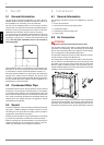
5.3 Sound
To prevent solid-borne sound from being transmitted to the heat-
ing system, a vibration-damped connection should be used for
connecting the heat pump with the heating system (install the
supplied hose connections free of strain).
Installed air ducts should be sound-isolated from the heat pump
to prevent the transmission of solid-borne sound to the ducts.
If both air openings are connected directly to a wall opening, the
ventilator terminals can be reversed from a delta to a star con-
nection (see information in the ventilator terminal box).
6 Installation
6.1 General Information
The following connections need to be established on the heat
pump:
Fresh and exhaust air
Flow and return flow of the heating system
Condensate outflow
Outflow for the pressure relief valve
Power supply
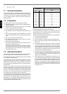
6.2 Air Connection
ATTENTION!
Do not restrict or block the area around the air intake or outlet.
The air intake opening of the device is solely designed for direct
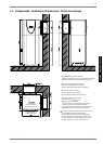
connection to a wall opening. The wall opening can be provided
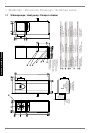
with air duct and sealing collar for this purpose. See the illustra-
tion in the appendix under Installation Dimensions.
The glass fibre reinforced concrete air ducts offered as accesso-
ries are moisture-resistant and diffusion-free.
The sealing collar is used to seal the air ducts on the heat pump.
The air ducts are not screwed directly onto the heat pump. Only
the rubber seal comes into direct contact with the heat pump
when the system is installed correctly. This guarantees easy as-
sembly and disassembly of the heat pump and also ensures that
solid-borne sound is well insulated.
It must also be ensured that the interior side of the wall opening
is lined with thermal insulation to prevent the wall from becoming
cold and to prevent moisture from penetrating the wall. The en-
closed fixing accessories can be used for attachment to the wall.
P
P