


www.dimplex.de E-4
English
4
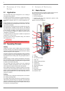
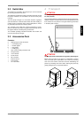
3.2 Switch Box
The switch box is located in the heat pump. It can be accessed
by removing the lower front cover.
The switch box contains the supply connection terminals, as well
the power contactors, the soft starter unit and the heat pump
manager.
The heat pump manager is a convenient electronic regulation
and control device. It controls and monitors the entire heating or
cooling system on the basis of the external temperature, includ-
ing hot water preparation and safety systems.
The customer must install the external temperature sensor,
which is included in the scope of supply of the heat pump control-
ler together with the necessary fixing accessories.
The enclosed operating instructions describe the function and
use of the heat pump manager.
3.3 Accessories Pack
Contents:
2 Sealing rings for duct connection
3 1" connecting hoses
3 1" double nipples
6 1" flat gaskets
1 1" sealing plug
1 Hose nozzle for filling and drain cock
2 Fixing brackets
2 10-mm dowels
2 8 x 80 screws
4 M4 x 8 screws
1 External sensor
1 6-mm dowels
1 4.5 x 50 screws
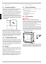
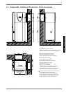
4 Transport
ATTENTION!
When transporting the heat pump, ensure that it is not tilted more than
45° (in any direction).
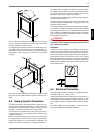
Use a wooden pallet for transporting the heat pump to the final in-
stallation location. The basic device can be transported with a lift
truck, hand truck or by means of 3/4" pipes fed through the holes
in the base plate or frame.
ATTENTION!
The heat pump and the wooden pallet are only joined by the packing film.
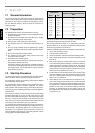
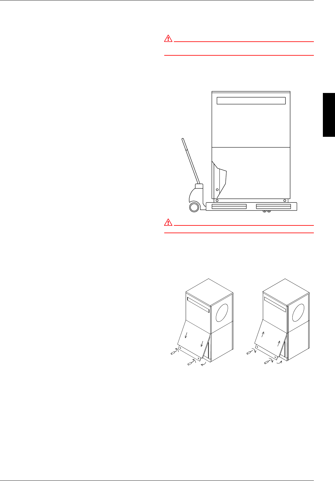
Before using the holes in the frame, it is advisable to remove
each of the side panel assemblies. This is done by loosening
each of the two screws at the base and then withdrawing the
panels by unhooking them from above. Rehang the panels by
gently pushing them in an upwards direction.
Opening the cover Closing the cover