


108117-01G
For more information, visit www.desatech.com
For more information, visit www.desatech.com
14
INSTALLATION
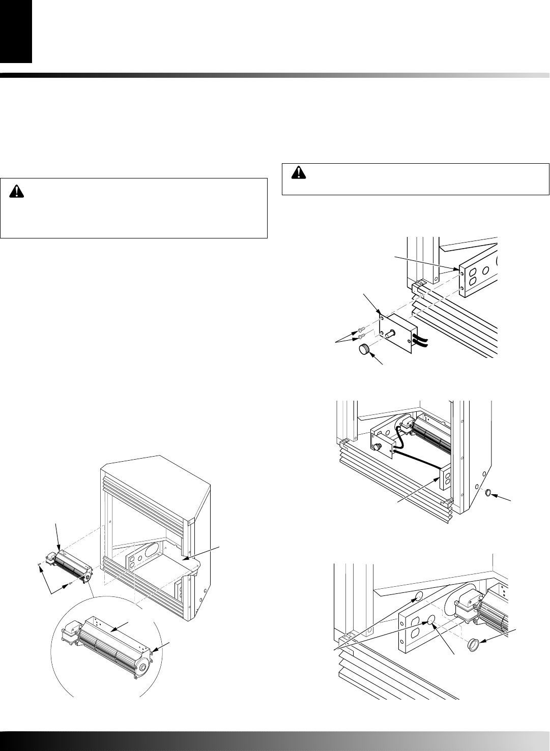
Installing Thermostatic Blower Accessory (Cont.)
INSTALLATION
Continued
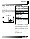
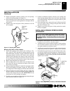
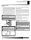
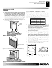
10. Place control knob provided on plastic control shaft of speed
control (see Figure 20).
11. Mount the speed control onto the front leg of the left floor
support bracket using 2 screws provided (see Figure 20).
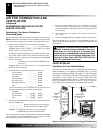
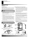
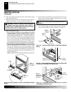
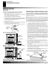
Blower
#8 Screws
Lower
Rear Wall
of Firebox
Exhaust
Port
Top
Mounting
Tab
Control Knob
Screws
Speed
Control
Floor
Support
Bracket
Figure 20 - Attaching Speed Control (VTGF33NR/VTGF33PR
Shown)
13. Check to make sure that the power cord and all wires are com-
pletely clear of the blower wheel and that there are no other
foreign objects in blower wheel.
12. Plug in blower power cord.
a. If your firebox is installed as a freestanding unit with an
accessory mantel, determine whether the power cord will
exit the left side or the right side of the firebox. Install one
plastic bushing provided into the 1
1
/2" hole in the floor sup-
port on the exit side. Install the second bushing provided into
the 1
1
/2" hole in the outer casing through which the power
cord will exit (see Figures 21 and 22). Route power cord
through plastic bushings and plug the power cord into a prop-
erly grounded three-prong wall receptacle near the firebox.
b.If your fireplace system installation is recessed and if an
outlet is not installed in your fireplace, you must install
the GA3555 Outlet kit with cover in your fireplace which
will supply a convenient 3-prong grounded electrical outlet
for your blower. Refer to the installation manual provided
with the model GA3555 accessory for instructions on wir-
ing the duplex outlet.
Note:
A qualified installer must make all electrical connections.
WARNING: Failure to connect all wires properly
as indicated may cause electrical short circuit or
personal injury. A qualified electrician should check
that all connections are made properly.
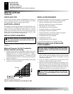
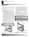
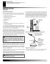
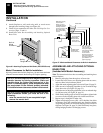
Figure 21 - Installing Plastic Bushing for Power Cord (Right Side
Exit Shown) (VTGF33NR/VTGF33PR Shown)
Right Floor
Support Bracket
Plastic
Bushing
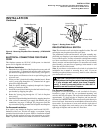
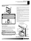
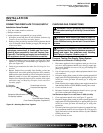
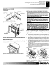
Figure 22 - Installing Bushings (Left Side Exit shown)
(VTGF33NR/VTGF33PR Shown)
Bushing Location
for Recessed
Installation
Bushing
Location for
Freestanding
Installation
Plastic
Bushing
14. Peel off backing paper and stick supplied wiring diagram de-
cal near center of firebox bottom (see Figure 23, page 15).
CAUTION: Never touch the blower wheel while in
operation.
Figure 19 - Mounting Blower to Firebox (VTGF33NR/VTGF33PR
Shown)