


108117-01G
For more information, visit www.desatech.com
For more information, visit www.desatech.com
17
17
➞
➞
INSTALLATION
Connecting Fireplace To Gas Supply (Cont.)
Checking Gas Connections
INSTALLATION
Continued
Installation Items Needed
• 5/16" hex socket wrench or nut-driver
• Phillips screwdriver
• sealant (resistant to propane/LP gas, not provided)
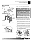
1. If fireplace screen and floor are still installed, see Removing
Fireplace Screen and Floor Assembly, page 8.
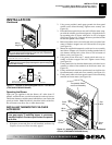
2. Route gas line (provided by installer) from equipment shutoff
valve to fireplace. Route flexible gas supply line through one
of the access holes.
CONNECTING FIREPLACE TO GAS SUPPLY
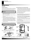
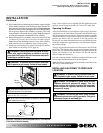
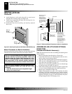
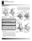
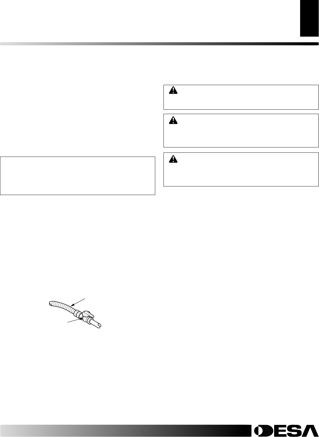
3. Attach the flexible gas line to gas supply (see Figure 26). Check
tightness of flexible gas line attached to gas regulator of fire-
place (see Figure 26).
4. Check all gas connections for leaks. See Checking Gas Con-
nections.
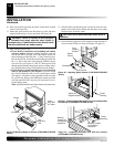
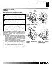
5. Replace fireplace floor assembly. Feed flexible gas line into
fireplace base area while replacing fireplace floor assembly.
Make sure the entire flexible gas line is in fireplace base area.
Note:
Be careful of wires and components on underside of
fireplace floor. Reattach fireplace floor assembly with screws
removed in step 3 of Removing Fireplace Screen and Floor
Assembly, page 8.
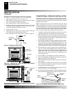
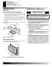
NOTICE: Most building codes do not permit con-
cealed gas connections. A flexible gas line is pro-
vided to allow accessibility from the fireplace (see
Figure 26). The flexible gas supply line connection to
the equipment shutoff valve should be accessible.
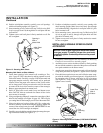
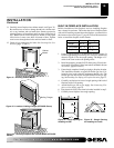
Figure 26 - Attaching Gas Lines Together
From Gas Meter (Natural)
From External Regulator (Propane/LP)
Flexible Gas Line from
Fireplace Gas Regulator
To Fireplace
Gas Regulator
Equipment Shutoff Valve
Provided by Installer
Pressure Testing Gas Supply Piping System
Test Pressures In Excess Of 1/2 PSIG (3.5 kPa)
1. Disconnect appliance with its appliance main gas valve (con-
trol valve) and equipment shutoff valve from gas supply pip-
ing system. Pressures in excess of 1/2 psig will damage fire-
place gas regulator.
2. Cap off open end of gas pipe where equipment shutoff valve
was connected.
3. Pressurize supply piping system by either opening propane/LP
supply tank valve for propane/LP gas or opening main gas valve
located on or near gas meter for natural gas, or using com-
pressed air.
4. Check all joints of gas supply piping system. Apply noncorrosive
leak detection fluid to all joints. Bubbles forming show a leak.
5. Correct all leaks at once.
6. Reconnect fireplace and equipment shutoff valve to gas sup-
ply. Check reconnected fittings for leaks.
Test Pressures Equal To or Less Than 1/2 PSIG (3.5 kPa)
1. Close equipment shutoff valve (see Figure 27, page 18).
2. Pressurize supply piping system by either opening propane/LP
supply tank valve for propane/LP gas or opening main gas valve
located on or near gas meter for natural gas, or using com-
pressed air.
3. Check all joints from gas meter for natural or propane/LP sup-
ply to equipment shutoff valve (see Figures 28 or 29, page 18).
Apply noncorrosive leak detection fluid to all joints. Bubbles
forming show a leak.
4. Correct all leaks at once.
CHECKING GAS CONNECTIONS
WARNING: Test all gas piping and connections
for leaks after installing or servicing. Correct all leaks
at once.
WARNING: Never use an open flame to check for
a leak. Apply a noncorrosive leak detection fluid to all
joints. Bubbles forming show a leak. Correct all leaks
at once.
WARNING: For propane/LP units, make sure exter-
nal regulator has been installed between propane/LP
supply and heater. See guidelines under
Installing
Gas Piping to Fireplace Location
, page 15.