


www.desatech.com
114370-02C6
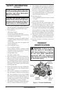
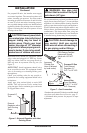
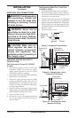
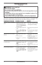
Figure 4 - Attaching Damper Clamp
Manufactured
Fireplace
Masonry
Fireplace
Damper
Damper
Clamp
Damper
Damper
Clamp
Damper
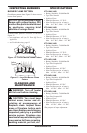
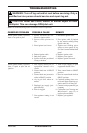
VENTING SPECIFICATIONS FOR
INSTALLATION
The replace chimney ue and vent must be draft-
ing properly. To check the vent for proper drafting:
Light a tightly rolled newspaper on one end and
place it at the inside front edge of the replace.
Observe the smoke and be sure the vent is properly
drawing it up the chimney. If the smoke spills out
into the room, extinguish the ame and remove any
obstruction until proper venting is achieved.
The chimney ue must have a minimum free air
opening of 43" during operation of this log set.
A damper clamp is provided to x the damper in
position.
The minimum ue sizes shown in Figure 2 are
based on a 6' chimney height using round pipe. Your
minimum ue size will vary based on input rate and
chimney height. Refer to the National Fuel Gas Code
ANSI Z223.1/NFPA 54, Section 6.6, for details.
INSTALLING DAMPER CLAMP
Secure the damper stop clamp to the edge of the
damper as shown in Figure 4. If for any reason this
clamp doesn't work on your replace, another suit-
able clamp or permanent stop must be installed, or
the damper blade must be cut or removed.
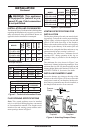
MODEL BURNER
BTU
INPUT
MINIMUM
VENT
OPENING
VTD-18NV-JHB
VTD-18PV-JHB
18" Ramp 59,000 8" dia.
VTD-24NV-JHB
VTD-24PV-JHB
24" Ramp 69,000 8" dia.
VTD-30NV-JHB
VTD-30PV-JHB
30" Ramp 74,000 8" dia.
INSTALLATION
Continued
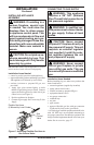
MINIMUM FIREBOX SIzES
MODEL
FRONT
WIDTH
BACK
WIDTH*
DEPTH
HEIGHT
VTD-18NV-JHB
VTD-18PV-JHB
28" 16" 14" 18"
VTD-24NV-JHB
VTD-24PV-JHB
29
3
/
4
" 20" 15
1
/
2
" 18"
VTD-30NV-JHB
VTD-30PV-JHB
36" 27" 18" 18"
*At depth indicated
BURNER ORIFICE
LOG
SIzE
NATURAL PROPANE/LP
INCHES NO. INCHES NO.
18" 0.1495 25 0.0935 42
24" 0.1570 22 0.0980 40
30" 0.1660 19 0.1015 38
SPECIFICATIONS (W.C.)
FUEL INLET PRESSURE
MANIFOLD
PRESSURE
MIN. MAX.
NG 5" 10.5" 3.5
LP 11" 14" 10
Figure 3 - Specications
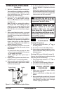
WARNING: This appliance
is equipped for (natural or pro-
pane/LP) gas. Field conversion
is not permitted.
INSTALLATION AND CLEARANCES
The charts in Figure 2 indicate technical information
regarding the installation of your gas log set. Please
make sure that all of the specications shown are
applicable before installation is attempted.
Figure 2 - Technical Information Charts
FLUE OPENING SPECIFICATIONS
Note: This vented appliance must be installed
only in a solid-fuel burning replace constructed
of noncombustible material. The replace must
include a ue and venting system with the mini-
mum openings shown in Figure 3.