


111826-02F
For more information, visit www.desatech.com
9
9
INSTALLATION
Continued
INSTALLATION
Connnecting to Gas Supply (cont.)
Checking Gas Connections
Pressure Testing Gas Supply Piping System
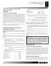
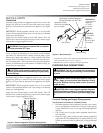
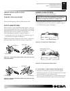
Propane/LP
Supply Tank
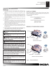
External Regulator
Figure 8 - External Regulator With Vent Pointing Down
Vent Pointing Down
WARNING: Use pipe joint seal ant that is resistant
to liquid pe tro leum (LP) gas.
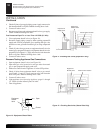
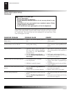
We recommend that you install a sediment trap in sup ply line as
shown in Figure 9, depending on your model. Locate sed i ment
trap where it is with in reach for cleaning. Install in piping system
between fuel supply and appliance. Locate sed i ment trap where
trapped mat ter is not likely to freeze. A sediment trap traps mois-
ture and con tam i nants. This keeps them from going into appliance
controls. If sediment trap is not in stalled or is installed wrong, ap-
pliance may not run properly.
CAUTION: Avoid damage to gas control. Hold gas
control with wrench when connecting it to gas piping
and/or fi ttings.
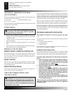
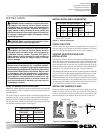
Figure 9 - Gas Connection
Gas Control
Pipe Cap Tee
Nipple Joint
3" Minimum
Sediment Trap
PROPANE/LP
- From External
Regulator
(11" W.C.**
to 14" W.C.
Pressure)
NATURAL
- From Gas
Meter
(5" W.C.**
to 10.5" W.C.
Pressure)
CSA Design-Certifi ed Equipment
Shutoff Valve With 1/8" NPT Tap*
Approved Flexible
Gas Hose (if allowed
by local codes)
* Purchase the optional CSA design-cer ti fi ed equipment shutoff valve
from your dealer. See Accessories, page 22.
**Minimum inlet pressure for purpose of input adjustment.
WARNING: Test all gas pip ing and connections
for leaks after in stall ing or serv ic ing. Cor rect all leaks
at once.
WARNING: Never use an open fl ame to check for
a leak. Apply a noncorrosive leak detection fl u id to
all joints. Bub bles form ing show a leak. Correct all
leaks at once.
CAUTION: Make sure ex ter nal regulator has been
installed between propane/LP supply and appliance.
See guidelines under Con nect ing to Gas Sup ply, page
8.
Pressure Testing gas Supply Piping system
Test Pressures In Excess Of 1/2 PSIG (3.5 kPa)
1. Disconnect appliance with its appliance main gas valve (control
valve) and equip ment shutoff valve from gas sup ply pip ing
sys tem. Pres sures in ex cess of 1/2 psig will dam age appliance
reg u la tor.
2. Cap off open end of gas pipe where equip ment shutoff valve
was con nect ed.
3. Pressurize supply pip ing sys tem by ei ther opening pro pane/LP
sup ply tank valve for propane/LP gas or opening main gas valve
lo cat ed on or near gas meter for natural gas, or using com pressed
air.
CHECKING GAS CONNECTIONS
Installation must include an equipment shutoff valve, union, and
plugged 1/8" NPT tap. Locate NPT tap within reach for test gauge
hook up. NPT tap must be up stream from appliance (see Figure
9).
IMPORTANT: Install equipment shutoff valve in an ac ces si ble
lo ca tion. The equip ment shutoff valve is for turning on or shut ting
off the gas to the appliance.
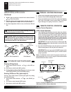
Apply pipe joint sealant lightly to male NPT threads. This will
prevent excess sealant from going into pipe. Excess sealant in pipe
could result in clogged appliance valves.
Installation must include an equipment shutoff valve, union, and
plugged 1/8" NPT tap. Locate NPT tap within reach for test gauge
hook up. NPT tap must be up stream from appliance (see Figure
9).
IMPORTANT: Install equipment shutoff valve in an ac ces si ble
lo ca tion. The equip ment shutoff valve is for turning on or shut ting
off the gas to the appliance.
Apply pipe joint sealant lightly to male NPT threads. This will
prevent excess sealant from going into pipe. Excess sealant in pipe
could result in clogged appliance valves.