


111826-02F
For more information, visit www.desatech.com
7
7
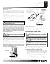
WARNING: Before installing in a solid fuel burn-
ing fi replace, the chimney fl ue and fi rebox must be
cleaned of soot, creosote, ash es and loose paint by
a qual i fi ed chim ney cleaner. Creosote will ignite if
highly heated. A dirty chimney fl ue may create and
dis trib ute soot within the house. In spect chim ney fl ue
for damage. If damaged, repair fl ue damper before
operating appliance.
INSTALLATION AND CLEARANCES
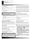
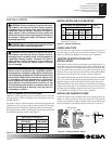
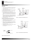
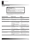
LOG SIZING REQUIREMENTS Min.
Minimum Firebox Size Flue size
Log Front Rear*
Size Height Depth Width Width
18" 17" 14" 24" 20" 8"
24" 17" 14" 28" 22" 8"
*Measured at 14" depth
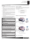
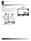
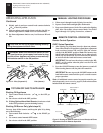
Damper Clamp
Damper
Clamp
Damper
Manufactured
Fireplace
Masonry Fireplace
Figure 6 - Attaching Damper Clamp
Damp er
Damper
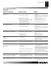
INSTALLATION
Flue Opening Specifi cations
Installation and Clearances
Venting Specifi cations for Installation
Installing Damper Clamp
INSTALLATION
WARNING: Before installing in a solid fuel burn-
ing fi replace, the chimney fl ue and fi rebox must be
cleaned of soot, creosote, ash es and loose paint by
a qual i fi ed chim ney cleaner. Creosote will ignite if
highly heated. A dirty chimney fl ue may create and
dis trib ute soot within the house. In spect chim ney
fl ue for damage.
NOTICE: Installation, service, and repair of this ap-
pli ance must be performed by a qualifi ed in stall er,
ser vice agency, com pa ny or gas supplier ex pe ri enced
with this type of gas ap pli ance. Only fac to ry au tho rized
components list ed in these in struc tions may be used
in ac cor dance with the man u fac tur er’s in struc tions
and all codes and requirements of the authority hav-
ing ju ris dic tion. Any modifi cations to this kit, or use
of unauthorized com po nents or ac ces so ry items will
void the man u fac tur er’s war ran ty, and may result in
a haz ard ous condition.
FLUE OPENING SPECIFICATIONS
Note: This vented appliance must be in stalled only in a solid-fuel
burning fi replace with a working fl ue and constructed of non com -
bus ti ble material.
The charts in Figure 4 indicate technical in for ma tion regarding the
installation of your gas log set. Please make sure that all of the spec-
i fi ca tions shown are applicable be fore in stal la tion is at tempt ed.
The fi replace must include a working fl ue and venting system with
the minimum open ings shown in the Figure 5.
CHECK GAS TYPE
Use the correct gas type (natural or propane/LP) for your unit. If
your gas supply is not correct, do not instal in fi replace. Call dealer
where you bought the appliance for proper type of appliance.
VENTING SPECIFICATIONS FOR
INSTALLATION
The fi replace chimney fl ue and vent must be draft ing properly. To
check the vent for proper drafting: Light a tightly rolled news pa per
on one end and place it at the inside front edge of the fi replace. Ob-
serve the smoke and be sure the vent is properly drawing it up the
chimney. If the smoke spills out into the room, extinguish the fl ame
and remove any obstruction until proper venting is achieved.
The chimney fl ue damper must be fi xed open to provide a min i mum
of 43 sq. in. of free air opening during operation of this log set. A mul-
tipurpose damper clamp is provided to fi x the damper in position.
The minimum fl ue sizes shown in Figure 5 are based on a 6' chimney
height using round pipe. Your minimum fl ue size will vary based
on input rate and chimney height. Refer to the National Fuel Gas
Code ANSI Z223.1/NFPA 54, Section 6.6, for details.
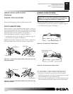
INSTALLING DAMPER CLAMP
Secure the damper stop clamp provided to the leading edge of the
damper as shown in Figure 6. If for any reason this clamp doesn't
work on your fi replace, an oth er suitable clamp or permanent stop
must be installed, or the damper blade must be cut or removed.
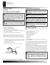
WARNING: Make sure the selector switch is in the
OFF po si tion before installing appliance .
Figure 4 - Technical Information Charts
SPECIFICATIONS (W.C.)
FUEL INLET MANIFOLD
PRESSURE PRESSURE
Min. Max.
NG 7 10.5 3.5
LP 11 14 10
Figure 5 - Sizes & Clearances