


111826-02F
For more information, visit www.desatech.com
8
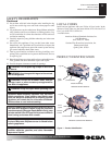
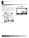
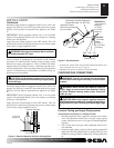
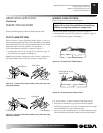
Figure 7 - Attaching Flexible Gas Hose to Gas Regulator
Gas Control
Flexible Gas
Hose (if allowed
by local codes)
WARNING: This appliance requires a 3/8" NPT
(National Pipe Thread) inlet connection to the pres-
sure regulator.
WARNING: A qualifi ed ser vice per son must con nect
appliance to gas sup ply. Follow all local codes.
CAUTION: Never connect propane/LP fi replace
directly to the propane/LP supply. This unit re quires
an external regulator (not supplied). Install the external
regu la tor be tween the unit and propane/LP supply.
WARNING: Never connect natural gas fi replace to
pri vate (non-utility) gas wells. This gas is com mon ly
known as wellhead gas.
Installation Items Needed
Before installing appliance, make sure you have the items listed
below.
• external regulator (supplied by installer)
• piping (check local codes)
• sealant (resistant to propane/LP gas)
• equipment shutoff valve *
• test gauge connection *
• sediment trap
• tee joint
• pipe wrench
• approved fl exible gas line with gas con nec tor (if allowed by lo cal
codes) (provided)
* A CSA design-certifi ed equipment shutoff valve with 1/8" NPT
tap is an ac cept able alternative to test gauge con nec tion. Pur chase
the optional CSA design-certifi ed equipment shutoff valve from
your dealer. See Accessories, page 22.
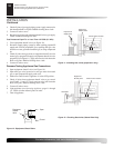
For propane/LP units, the installer must supply an external reg u -
la tor. The external reg u la tor will reduce incoming gas pressure. You
must reduce in com ing gas pressure to between 11 and 14 inches of
water. If you do not reduce in com ing gas pressure, regulator dam-
age could occur. Install external reg u la tor with the vent point ing
down as shown in Figure 8 page 9. Pointing the vent down protects
it from freezing rain or sleet.
CAUTION: Use only new, black iron or steel pipe.
In ter nal ly-tinned copper tubing may be used in cer-
tain areas. Check your local codes. Use pipe of 1/2"
di am e ter or greater to allow prop er gas vol ume to
appliance. If pipe is too small, undue loss of volume
will occur.
CONNECTING TO GAS SUPPLY
INSTALLATION
Continued
INSTALLATION
Installing Appliance Assembly
Connecting To Gas Supply
WARNING: If installing in a sunken fi re place, spe-
cial care is needed. You must raise the fi re place fl oor
to allow access to appliance control panel. This will
in sure ad e quate air fl ow and guard against soot ing.
Raise fi replace fl oor with noncom bus ti ble ma te ri al.
Make sure material is secure.
CAUTION: Do not pick up appliance as sem bly by
logs. This could damage unit. Only handle assembly
by grates.
IMPORTANT: Make sure the appliance is level. If unit is not level,
unit will not work properly.
Installation Items Needed
• control cover kit (provided with appliance)
• approved fl exible gas hose and fi ttings (pro vid ed with appliance)
(if al lowed by lo cal codes)
• sealant (resistant to propane/LP gas, not pro vid ed)
Note: Install optional Hand-Held Remote Control Kit (see Ac ces -
so ries, page 22) before in stall ing gas log appliance (Remote-Ready
Models Only). See installation in struc tions in clud ed with the kit.
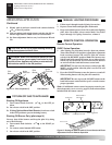
1. Apply pipe joint sealant lightly to male threads of gas fi tting
(not provided). Connect ap proved fl exible gas hose to inlet side
of gas con trol (see Figure 7).
2. Position appliance in fi re place.
3. Connect to gas supply. See Con nect ing To Gas Supply.
INSTALLING APPLIANCE ASSEMBLY