


www.desatech.com
124002-01C 17
OPERATION
Continued
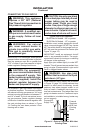
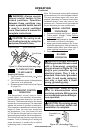
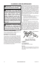
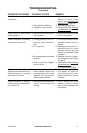
BURNER FLAME PATTERN
WARNING: If yellow tipping
occurs, your heater could pro-
duce increased levels of carbon
monoxide.
NOTICE: Do not mistake orange
ames with yellow tipping. Dirt
or other ne particles enter the
heater and burn causing brief
patches of orange ame.
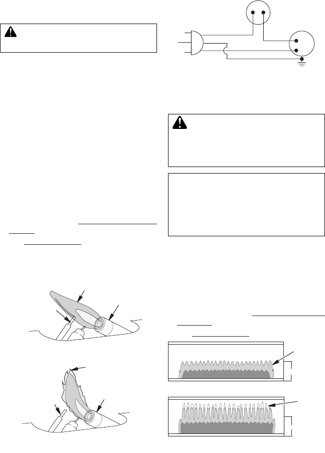
Figure 26 shows a correct burner ame pattern.
Figure 27 shows an incorrect burner ame pat-
tern. The incorrect burner ame pattern shows
yellow tipping of the ame. It also shows the
ame higher than 1/2 the glass panel height.
If burner ame pattern is incorrect, as shown
in Figure 27
• turn heater off (see To Turn Off Gas To
Appliance, page 16)
• see Troubleshooting, page 19
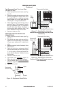
INSPECTING HEATER
Figure 25 - Incorrect Pilot Flame Pattern
Figure 24 - Correct Pilot Flame Pattern
Figure 26 - Correct Burner Flame Pattern
Yellow
Tipping
Figure 27 - Incorrect Burner Flame Pattern
1
/2 Glass
Height
1
/2 Glass
Height
Blue
Flame
Check pilot ame pattern and burner ame
pattern often.
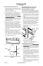
PILOT FLAME PATTERN
Figure 24 shows a correct pilot ame pattern.
Figure 25 shows an incorrect pilot ame pat-
tern. The incorrect pilot ame is not touching
the thermocouple. This will cause the thermo-
couple to cool. When the thermocouple cools,
the heater will shut down.
If pilot ame pattern is incorrect, as shown
in Figure 25
• turn heater off (see To Turn Off Gas to Ap-
pliance, page 16)
• see Troubleshooting, page 19
Note: The pilot ame on natural gas units will
have a slight curve, but ame should be blue
and have no yellow or orange color.
Thermocouple
Pilot Burner
Pilot Burner
Thermocouple
Blue Flame
Yellow Flame
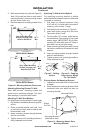
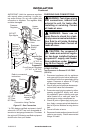
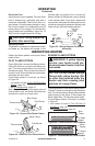
Extension Cord
Use extension cord if needed. The cord must
have a three-prong, grounding plug and a
three-hole receptacle. Make sure cord is in
good shape. It must be heavy enough to carry
the current needed. An undersized cord will
cause a drop in line voltage. This will result in
loss of power and overheating. Use a No. 16
AWG cord for lengths less than 50 feet.
CAUTION: Verify proper op-
eration after servicing.
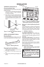
Operating Blower
The blower is connected to a thermostat. When
unit heats up, the blower will operate. A few
Figure 23 - Wiring Diagram For Blower
Accessory
Thermostat
Sensor
Switch
Green
White
Green
White
1 10/115
V.A.C.
Blower
Motor
Black
Black
minutes after unit cycles off or is turned off,
blower will shut off. Blower will cycle on and off
in this manner. Note: If you have a heater with
a thermostat, the heater and blower will not turn
off and on at exactly the same time. Blower cycle
times will vary with heat setting selected.