


107032-01F
For more information, visit www.desatech.com
For more information, visit www.desatech.com
22
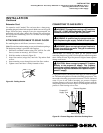
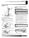
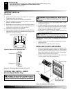
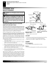
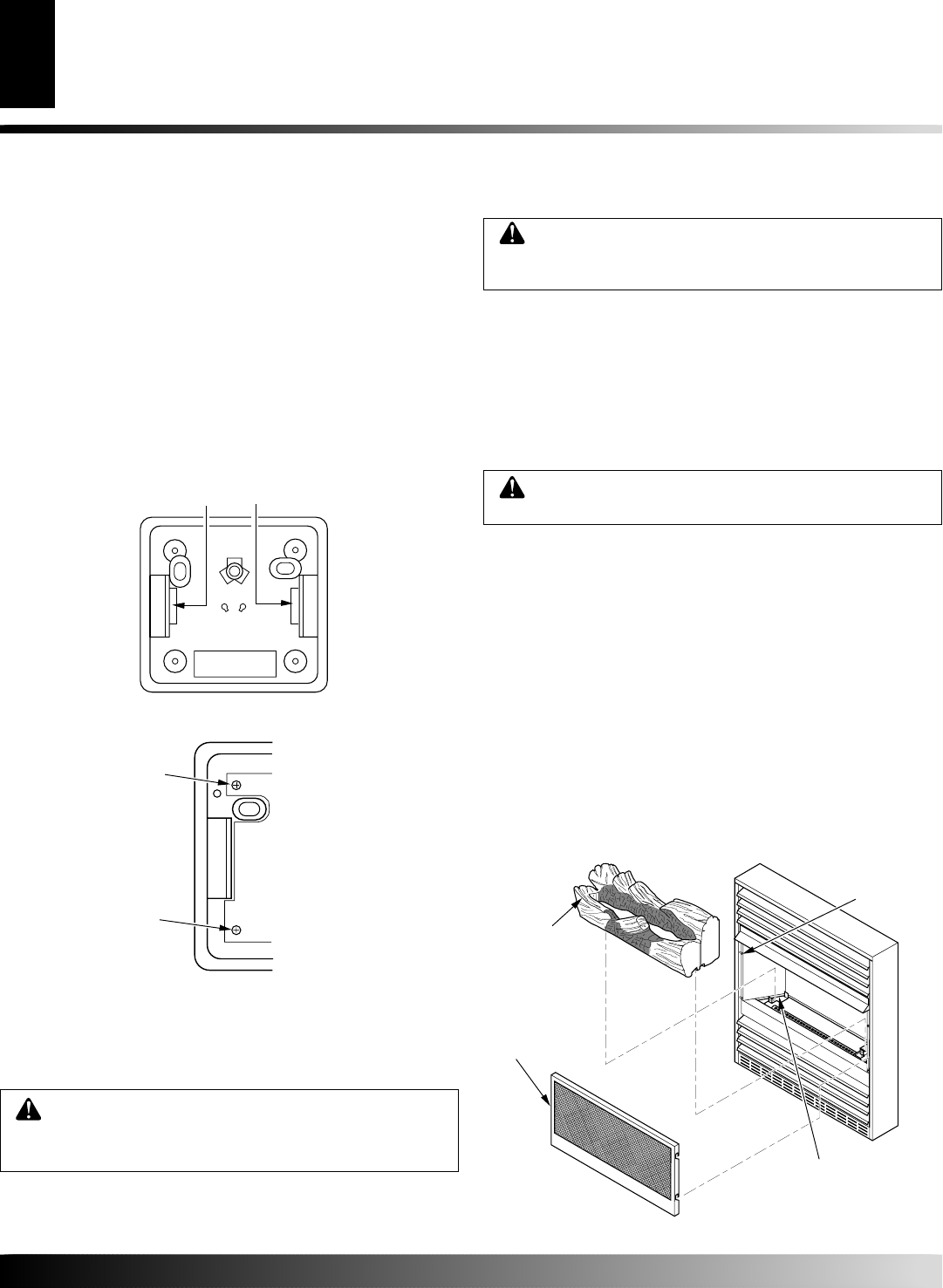
1. Remove log packaging material and discard packaging. Gen-
tly place log on burner support (see Figure 44). The log should
fit flat against top of burner support and log locator tabs fit
into the slots under the log. Do not allow log to contact flame.
If flame contacts log, soot will be created.
2. Reattach screen by placing the notches in the screen frame
over the shoulder screws and pushing down.
INSTALLING LOG SET AND SCREEN
Figure 44 - Installing Log and Screen
Log
Shoulder Screw
Screen
Burner Support with
Log Locator Tabs
INSTALLATION
Continued
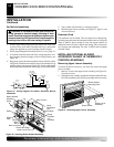
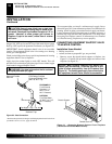
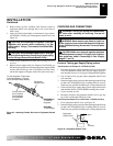
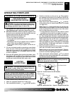
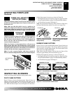
6. Connect one bare wire end to each terminal (“W” and “R”) of
the thermostat base (see Figure 43).
7. Install the base onto the wall with the provided screws.
8. Move the temperature adjustment back and forth to insure the
bimetal is free from restrictions.
9. Replace the cover onto the base. (Upon installation, the ther-
mostat must be allowed to stabilize at room temperature for
a minimum of 30 minutes for proper operation).
10. Set switch on fireplace to Auto position.
11. Set the temperature adjustment to the desired setting. This ther-
mostat has been electronically calibrated at the factory. No ad-
justment or leveling is necessary.
Figure 42 - Back View of Thermostat Base
Feed wires through rectangular slots
W
R
Figure 43 - Thermostat Base Terminals “W” and “R”
Terminal “W”
Terminal “R”
OPTIONAL WALL SWITCH - GWMS2
(Remote-Ready Models Only)
WARNING: Do not connect this switch to any
electrical source! Electrical shock and/or fire hazard
will occur.
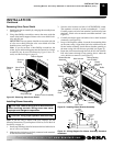
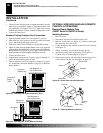
1.
Connect one terminal of 25 ft. wire to bottom contact of switch
(see Figure 41, page 21)
.
2. Connect remaining wire terminal to the “TH” terminal on the
control valve. Make sure that wire terminals are in the posi-
tions on your unit as pictured in Figure 41, page 21. If wires
are not “crossed” the thermostat will not work.
3.
Route the 25 ft. wire to a convenient location to mount your
wall switch (no outside walls).
WARNING: Do not connect the switch to a power
source. Electrical shock and/or fire hazard will occur.
WARNING: Read and follow installation instruc-
tions. Installation should be done by a qualified
installer familiar with low-voltage wiring procedures.
IMPORTANT:
The wire may be shortened but must not be
lengthened.
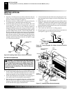
4. Connect one bare wire end to each of the terminals of the pro-
vided wall switch.
5. Install the wall switch and cover in the wall.
INSTALLATION
Optional Wall Mounted Thermostat - GWMT1 [Remote-Ready Models Only] (Cont.)
Optional Wall Switch - GWMS2 [Remote-Ready Models Only]
Installing Log Set and Screen