


107032-01F
For more information, visit www.desatech.com
For more information, visit www.desatech.com
14
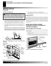
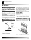
Red
Red
Fan Switch
(Auto/Off/On)
Blue
Blue
Thermostat
Switch
(N.O.)
Green
White
Green
White
On
110/115
V.A.C.
Blower
Motor
Black
Off
1
2
3
Auto
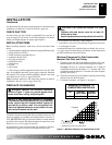
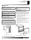
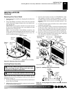
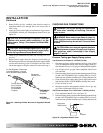
Figure 20 - Installing Blower Bracket Assembly
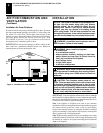
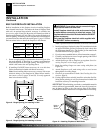
Figure 19 - Wiring Diagram For Blower Accessory Built-In
Installation
INSTALLATION
Continued
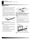
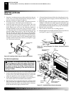
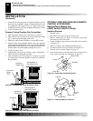
Figure 21 - Removing Upper Louver Assembly
Upper Louver
Assembly
Brass Screws
INSTALLING OPTIONAL BLOWER
ACCESSORY GA3450T IN THERMOSTAT-
CONTROLLED MODELS
Removing Upper Louver Assembly
To install the blower accessory, you must first remove the upper
louver assembly.
1. Remove 4 screws from upper louver assembly (see Figure 21).
Save these screws.
2. Pull upper louver assembly straight out from the cabinet. Be care-
ful not to scratch the paint. Set louver assembly and screws aside.
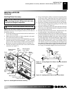
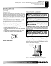
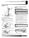
Blower Bracket
Mounting Holes
INSTALLATION
Installing Blower Accessory GA3450T in Remote-Ready Models (Cont.)
Installing Blower Accessory GA3450T in Thermostat-Controlled Models
For Built-In Installation
WARNING: A licensed electrician must connect the
wiring harness to electrical supply following all local
codes. Electrician must provide a clamp on the box cover
to secure the wiring. Wiring should be routed through the
bushing in the hole on the outer casing of fireplace.
1. Install a snap bushing found in hardware kit into one of the holes
on rear of valve cover shield. The other hole is for a strain relief
clamp (not supplied) to secure incoming electrical supply.
2. Follow steps 2 through 6 in Installing Blower Accessory, page 13.
3. A licensed electrician must follow the wiring diagram to con-
nect incoming electrical supply to fan kit wiring harness (see
Figure 19).
4. Plug power cord to the outlet receptacle (not provided) as shown
in Figure 20. Wind the extra cable in power cord and and tie it up
with the plastic wire strap (see Figure 20). Set the cable bundle
between the burner bracket and outer casing, away from the burner.
Blower Bracket
Assembly
Screw
Wire Harness
Plastic Wire Strap
Wire Harness
Switch
Plate
Switch
Clamp
Connector
(not
included)
Blue
Red
Outlet
Receptacle
(not
included)
Power Cord
Lower Louver Door
Black
5. Test to make sure the blower is working properly.
6. Reinstall upper louver assembly (see Figure 15, page 12) and
close lower louver.
Extension Cord
Use extension cord if needed. The cord must have a three-prong,
grounding plug and a three-hole receptacle. Make sure cord is in good
shape. It must be heavy enough to carry the current needed. An
undersized cord will cause a drop in line voltage. This will result in
loss of power and overheating. Use a No. 16 AWG cord for lengths
less than 50 feet.