


114745-01
For more information, visit www.desatech.com
11
11
INSTALLATION
Continued
INSTALLATION
Installing Heater Assembly (Cont.)
Connecting to Gas Supply
WARNING: This appliance requires a 3/8" NPT (National Pipe
Thread) inlet connection to the pressure regulator.
WARNING: A qualified service person must connect heater to gas
supply. Follow all local codes.
CAUTION: Never connect propane/LP fireplace directly to the
propane/LP supply. This heater requires an external regulator (not sup
-
plied). Install the external regulator between the heater and propane/LP
supply.
WARNING: Never connect natural gas fireplace to private (non-
utility) gas wells. This gas is commonly known as wellhead gas.
Installation Items Needed
Before installing heater, make sure you have the items listed below.
• external regulator (supplied by installer)
• piping (check local codes)
• sealant (resistant to propane/LP gas)
• equipment shutoff valve *
• test gauge connection *
• sediment trap
• tee joint
• pipe wrench
• approved flexible gas line with gas connector (if allowed by local codes)
(provided)
* A CSA design-certified equipment shutoff valve with 1/8" NPT tap is an
acceptable alternative to test gauge connection. Purchase the optional CSA
design-certified equipment shutoff valve from your dealer. See Accessories,
page 27.
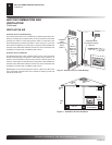
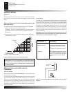
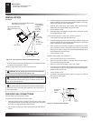
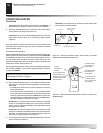
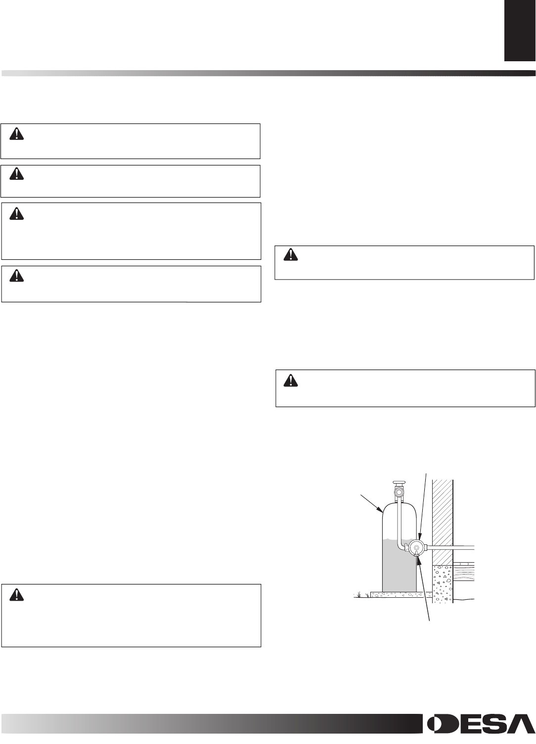
For propane/LP units, the installer must supply an external regulator. The
external regulator will reduce incoming gas pressure. You must reduce in
-
coming gas pressure to between 11 and 14 inches of water. If you do not
reduce incoming gas pressure, heater regulator damage could occur. Install
external regulator with the vent pointing down as shown in Figure 12. Point
-
ing the vent down protects it from freezing rain or sleet.
CAUTION: Use only new, black iron or steel pipe. Internally-tinned
copper tubing may be used in certain areas. Check your local codes.
Use pipe of 1/2" diameter or greater to allow proper gas volume to
heater. If pipe is too small, undue loss of volume will occur.
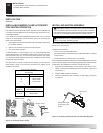
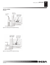
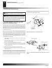
CONNECTING TO GAS SUPPLY
Installation must include an equipment shutoff valve, union, and plugged
1/8" NPT tap. Locate NPT tap within reach for test gauge hook up. NPT
tap must be upstream from heater (see Figure 13 page 12, depending on
your model).
IMPORTANT: Install equipment shutoff valve in an accessible location. The
equipment shutoff valve is for turning on or shutting off the gas to the ap
-
pliance.
Apply pipe joint sealant lightly to male NPT threads. This will prevent excess
sealant from going into pipe. Excess sealant in pipe could result in clogged
heater valves.
WARNING: Use pipe joint sealant that is resistant to liquid pe-
troleum (LP) gas.
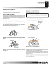
We recommend that you install a sediment trap in supply line as shown in
Figure 13 page 12, depending on your model. Locate sediment trap where it
is within reach for cleaning. Install in piping system between fuel supply and
heater. Locate sediment trap where trapped matter is not likely to freeze. A
sediment trap traps moisture and contaminants. This keeps them from going
into heater controls. If sediment trap is not installed or is installed wrong,
heater may not run properly.
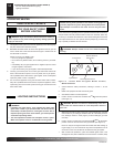
CAUTION: Avoid damage to gas control. Hold gas control with
wrench when connecting it to gas piping and/or fittings.
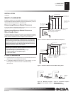
Control Valve to Supply Tank-Vanguard BT GRH/PV 019B
Propane/LP
Supply Tank
External Regulator
Figure 12 - External Regulator With Vent Pointing Down
Vent Pointing Down
114745-01