


7
104637
OWNER’S MANUAL
INSTALLATION
CAUTION: This fireplace cre-
ates warm air currents. These cur-
rents move heat to wall surfaces
next to fireplace. Installing fire-
place next to vinyl or cloth wall
coverings or operating fireplace
where impurities (such as to-
bacco smoke, aromatic candles,
cleaning fluids, oil or kerosene
lamps, etc.) in the air exist, may
discolor walls.
Note:
Your fireplace is designed to be used
in zero clearance installations. Wall or fram-
ing material can be placed directly against
any exterior surface on the rear, sides, or top
of your fireplace, except where stand-off
spacers are integrally attached. If stand-off
spacers are attached to your fireplace, these
spacers can be placed directly against wall
or framing materials.
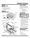
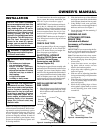
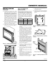
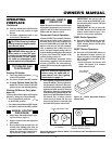
Figure 5 - Installing Deflector and Hood
WARNING: A qualified ser-
vice person must install fireplace.
Follow all local codes.
WARNING: Never install the
fireplace
• in a bedroom or bathroom
• in a recreational vehicle
• where curtains, furniture,
clothing, or other flammable
objects are less than 42 inches
from the front, top, or sides of
the fireplace
• in high traffic areas
• in windy or drafty areas
ASSEMBLING AND
ATTACHING OPTIONAL
BRASS TRIM
(Included with Mantel
Accessory or Purchased
Separately)
IMPORTANT:
If you are recessing the fire-
box in a wall, do not attach brass trim at this
time. See page 9 for built-in installation..
Note:
The instructions below show assem-
bling and attaching brass trim to fireplace.
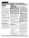
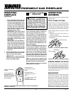
1. Remove packaging from three pieces
of brass trim.
2. Locate four brass screws, two adjust-
ing plates with set screws, and two
shims in the hardware packet.
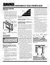
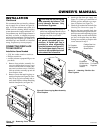
3. Align shim under adjusting plate as
shown in Figure 6.
4. Slide one end of adjusting plate/shim
in slot on mitered edge of top brass trim
(see Figure 6).
5. Slide other end of adjusting plate/shim
in slot on mitered edge of side brass
trim (see Figure 6).
6. While firmly holding edges of brass
trim together, tighten both set screws
on the adjusting plate with slotted
screwdriver.
NOTICE: This heater is intended
for use as supplemental heat. Use
this heater along with your pri-
mary heating system. Do not in-
stall this heater as your primary
heat source. If you have a central
heating system, you may run
system’s circulating blower while
using heater. This will help circu-
late the heat throughout the
house. In the event of a power
outage, you can use this heater
as your primary heat source.
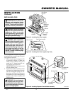
Use the dimensions shown for rough open-
ings to create the easiest installation. See
Built-In Fireplace Installation, page 9.
IMPORTANT:
Vent-free heaters add mois-
ture to the air. Although this is beneficial,
installing fireplace in rooms without enough
ventilation air may cause mildew to form
from too much moisture. See Air for Com-
bustion and Ventilation, pages 4 through 6.
IMPORTANT:
Make sure the fireplace is
level. If fireplace is not level, log set will not
work properly.
CHECK GAS TYPE
Use only propane/LP gas. If your gas supply
is not propane/LP gas, do not install fire-
place. Call dealer where you bought fire-
place for proper type fireplace.
ELECTRICAL HOOKUP
(Models GA3700 Series and
GA3700T Series Blower
Accessories, and GA3555
Internal Duplex Kit)
This fireplace accepts a blower assembly with
an electrical cord. The electrical cord is five feet
in length. You must locate fireplace within
reach of a 120 volt grounded electrical outlet. If
not, you must install an electrical outlet within
reach of fireplace power cord. The GA3555
outlet accessory may be used for built-in appli-
cations with blower accessory installed.
INSTALLING DEFLECTOR
AND HOOD
1. Place deflector on top of exhaust shroud
with triangular ends pointing out. Align
hole in deflector with center hole in lou-
ver panel.
Continued
Figure 6 - Assembling Brass Trim
Side Brass
Trim
Top
Brass
Trim
Slot
Mitered Edge
Slot
Shim
Set Screws
Adjusting
Plate
Deflector
Hood
Exhaust
Shroud
Louver Panel
2. Slide the hood on top of the deflector
and align the center hole with the holes
in the exhaust shroud and louver panel.
3. Using Phillip’s head screw provided,
insert the center screw through the hood,
deflector, and louver. See Figure 5.
4. Secure the hood with the remaining 2
screws provided.
Screws