


www.desatech.com 113084-01A
12
INSTALLATION
Continued
WARNING: Never connect
natural gas heater to private (non-
utility) gas wells. This gas is com-
monly known as wellhead gas.
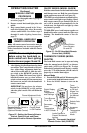
Installation Items Needed
Before installing heater, make sure you have the
items listed below.
• external regulator - propane/LP only (supplied
by installer)
• piping (check local codes)
• sealant (resistant to propane/LP gas)
• equipment shutoff valve *
• test gauge connection *
• sediment trap
• tee joint
• pipe wrench
* A CSA design-certified equipment shutoff valve
with 1/8" NPT tap is an acceptable alternative to
test gauge connection. Purchase the optional CSA
design-certified equipment shutoff valve from your
dealer. See Accessories, page 27.
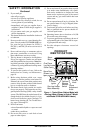
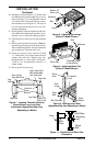
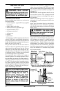
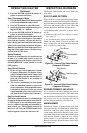
The gas inlet connection for the stove heater is
located on the lower right-hand side of the stove
when viewed from the front of the unit. The gas
connection can be made either through the bot-
tom right side or through the lower back opening
as illustrated in Figure 14. Make sure gas log heater
is secured to the stove cavity assembly.
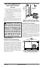
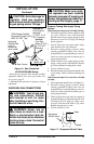
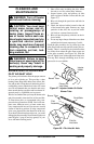
For propane/LP units, installer must supply an
external regulator. The external regulator will re-
duce incoming gas pressure. You must reduce in-
coming gas pressure to between 11 and 14 inches
of water. If you do not reduce incoming gas pres-
sure, heater regulator damage could occur. Install
external regulator with the vent pointing down as
shown in Figure 15. Pointing the vent down pro-
tects it from freezing rain or sleet.
CAUTION: Use only new, black
iron or steel pipe. Internally-tinned
copper tubing may be used in
certain areas. Check your local
codes. Use pipe of 1/2" diameter
or greater to allow proper gas
volume to heater. If pipe is too
small, undue loss of volume will
occur.
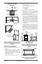
Figure 14 - Gas Regulator Location and
Gas Line Access Into Stove Cabinet
Gas Inlet
Connection
Access
Gas Log Heater
Back View
Side View
Figure 15 - External Regulator With Vent
Pointing Down
Back Stove
Panel
Stove Unit Front
Propane/LP
Supply Tank
External
Regulator
Vent
Pointing
Down
Installation must include a equipment shutoff
valve, union, and plugged 1/8" NPT tap. Locate
NPT tap within reach for test gauge hook up. NPT
tap must be upstream from heater (see Figure 16
on page 13).
IMPORTANT:
Install equipment shutoff valve in
an accessible location. The equipment shutoff
valve is for turning on or shutting off the gas to
the appliances.
Check your building codes for any special re-
quirements for locating equipment shutoff valve
to fireplaces.
Apply pipe joint sealant lightly to male threads.
This will prevent excess sealant from going into
pipe. Excess sealant in pipe could result in clogged
heater valves.
WARNING: Use pipe joint
sealant that is resistant to liquid
petroleum (LP) gas.
We recommend that you install a sediment trap in
supply line as shown in Figure 16, page 13. Lo-
cate sediment trap where it is within reach for
cleaning. Install in piping system between fuel
supply and heater. Locate sediment trap where
trapped matter is not likely to freeze. A sediment
trap traps moisture and contaminants. This keeps
them from going into heater controls. If sediment
trap is not installed or is installed wrong, heater
may not run properly.