


www.desatech.com
122527-01B6
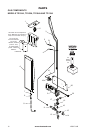
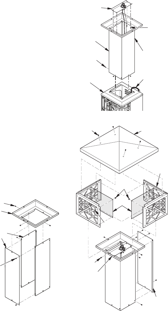
BURNER AND LIGHTPOST ASSEMBLY
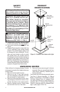
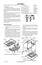
1. Locate 4 lightpost panels that are pack-
aged together. Assemble 3 of the pieces
with 4 screws (H) as shown in Figure 5.
2. Place lightpost top over panel assembly
aligning screw holes. Attach with 3 screws
(H) as shown in Figure 5.
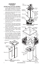
3. Pilot light and wiring has been placed
inside top of burner assembly for ship-
ping. Carefully remove pilot from inside
assembly and let wiring and pilot hang
down back of assembly.
4. Place pilot assembly on top of lightpost
top as shown in Figure 6. Attach with
4 screws (H). Check wire connections
before proceeding.
5. Place lightpost panels and top assembly
on top of burner assembly aligning back
side of each assembly. See Figure 6. At-
tach with 3 screws (H).
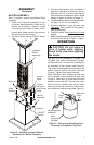
6. Attach 4 light shroud screens to light
shrouds with 4 screws (F) and 4 nuts (G)
each as shown in Figure 7. Only 2 of the
4 screens are shown.
7. Place deco light shrouds on top of light-
post top (see Figure 7). Make sure flanges
are on top. Slide shroud tabs together.
Attach to lightpost top with 4 screws (H)
through holes in bottom of shroud pieces
(see Figure 7). Tighten all screws.
8. Attach lightpost top cap to shroud assembly
with 4 screws (H) as shown in Figure 7.
ASSEMBLY
Continued
Deco
Light
Shroud
Figure 7 - Attaching Pilot and Shroud
Fourth
Lightpost
Panel
Lightpost
Top Cap
Lightpost
Top
Pilot Light
Wiring to
Back of
Heater
Figure 6 - Connecting Lightpost and
Burner Assembly
Burner
Assembly
Lightpost
Assembly
Open Side
of Panel
Assembly
to Back of
Heater
Figure 5 - Lightpost Panels and Top
Assembly
Lightpost
Panels
Lightpost
Top
Pilot
Assembly
Screen
Screw (H)
Screw (H)
Screw (H)
Screw (H)
Nut (G)
Screw (F)
Screw (H)
Screw
(H)