


www.desatech.com
11116307-01C
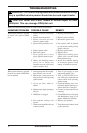
CHECKING GAS CONNECTIONS
WARNING: Test all gas piping
and connections, internal and
external to unit, for leaks after
installing or servicing. Correct
all leaks at once.
WARNING: Never use an
open ame to check for a leak.
Apply a noncorrosive leak detec-
tion uid to all joints. Bubbles
forming show a leak. Correct all
leaks at once.
CAUTION: For propane/LP
gas, make sure external regula-
tor has been installed between
propane/LP supply and heater.
See guidelines under Connect-
ing to Gas Supply, page 9.
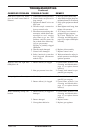
PRESSURE TESTING GAS SUPPLY
PIPING SYSTEM
Test Pressures In Excess Of 1/2 PSIG
(3.5 kPa)
1. Disconnect appliance with its appliance main
gas valve (control valve) and equipment
shutoff valve from gas supply piping system.
Pressures in excess of 1/2 psig will damage
heater regulator.
INSTALLATION
Continued
2. Cap off open end of gas pipe where equipment
shutoff valve was connected.
3. Pressurize supply piping system by either
opening propane/LP supply tank valve for
propane/LP gas or opening main gas valve
located on or near gas meter for natural gas
or using compressed air.
4. Check all joints of gas supply piping system.
Apply a noncorrosive leak detection uid to
all joints. Bubbles forming show a leak.
5. Correct all leaks at once.
6. Reconnect heater and equipment shutoff valve
to gas supply. Check reconnected ttings for
leaks.
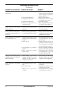
Test Pressures Equal To or Less Than 1/2
PSIG (3.5 kPa)
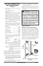
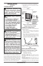
1. Close equipment shutoff valve (see Figure 12).
2. Pressurize supply piping system by either
opening propane/LP supply tank valve for
propane/LP gas or opening main gas valve
located on or near gas meter for natural gas
or using compressed air.
3.
Check all joints from gas meter for natural gas
or propane/LP supply tank for propane/LP gas,
to equipment shutoff valve (see Figure 13 or 14,
page 12). Apply a noncorrosive leak detection
uid to all joints. Bubbles forming show a leak.
4. Correct all leaks at once.
PRESSURE TESTING HEATER GAS
CONNECTIONS
1. Open equipment shutoff valve (see Figure 12).
2. For natural gas open main gas valve located
on or near gas meter. For propane/LP gas open
propane/LP supply tank valve.
3. Make sure control knob of heater is in the OFF
position.
4.
Check all joints from equipment shutoff valve to
thermostat gas valve (see Figure 13 or 14, page
12). Apply a noncorrosive leak detection uid
to all joints. Bubbles forming show a leak.
5. Correct all leaks at once.
6. Light heater (see Operating Heater, this page).
Check all other internal joints for leaks.
7. Turn off heater (see To Turn Off Gas to Appli-
ance, page 13).
8. Install refractory and front panel.
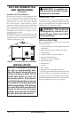
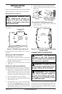
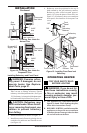
Install sediment trap in supply line as shown in
Figure 11, page 10. Locate sediment trap where
it is within reach for cleaning. Locate sediment
trap where trapped matter is not likely to freeze.
A sediment trap traps moisture and contaminants.
This keeps them from going into heater controls. If
sediment trap is not installed or is installed wrong,
heater may not run properly.
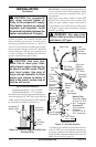
Install male connector and ex gas line to equipment
shutoff valve through hole provided in rear surround
as shown in Figure 11, page 10.
IMPORTANT: Hold the pressure regulator and
connector with wrench when connecting it to gas
piping and/or ttings. Do not over tighten pipe
connection to regulator. The regulator body could
be damaged.
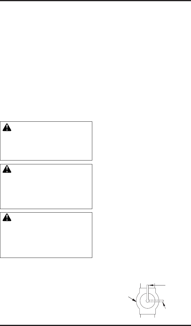
Figure 12 - Equipment Shutoff Valve
Open
Closed
Equipment
Shutoff Valve