


112126-01B
For more information, visit www.desatech.com
For more information, visit www.desatech.com
8
NOTICE: If installing blower in an existing stove
burner system with gas connections, shut off gas
supply and disconnect heater from gas supply. Con-
tact a qualified service person to do this.
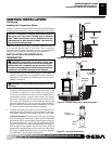
INSTALLING OPTIONAL BLOWER
ACCESSORY
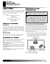
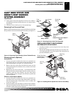
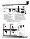
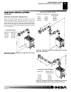
Figure 17 - Blower Assembly, Speed Control, and Thermal
Switch Locations
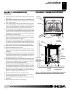
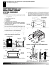
Figure 16 - Removing Rear Cover and Bottom Cover from Stove
Body
Speed
Control
Blower
Control
Knob
Locknut
Blower
Assembly
Thermal
Switch and
Bracket
Control
Shaft
TOP VIEW
Stove Body
Rear Cover
Bottom Cover
Hex
Screws
Mounting
Screws
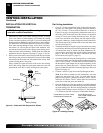
Mounting
Screws
Hex Screws
Mounting
Screws
Mounting Holes
Screws
Mounting
Holes
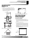
CAST IRON STOVE AND
DIRECT-VENT BURNER
SYSTEM ASSEMBLY
Continued
CAST IRON STOVE AND DIRECT-VENT BURNER SYSTEM ASSEMBLY
Installing Optional Blower Accessory
INSTALLING THE BLOWER
1. Remove 4 hex screws securing rear cover to back of stove body
(see Figure 16).
2. Separate bottom cover from rear cover by loosening the 8
mounting screws (see Figure 16).
3. Align the holes in the top mounting tabs of blower with the
holes in wall of rear cover. Using the 4 screws provided, mount
blower and tighten screws securely (see Figure 17).
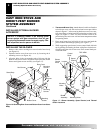
4.
Thermostat Blower Only: Attach thermal switch and bracket
to inside rear cover wall with two hex head screws provided as
shown in Figure 17. After securing bracket to rear cover, care-
fully bend along existing bend line on bracket to almost a 90°
angle (see Figure 17). This will allow thermal switch to be
positioned against stove rear wall and sense temperature when
in operating mode.
5. Place speed control on left inside of rear cover and push the
plastic control shaft through opening (see Figure 17).
6. While supporting speed control, secure control shaft with lock
nut by pushing and turning lock nut with pliers clockwise un-
til tight against the side of rear cover. Place control knob pro-
vided onto shaft.