


112126-01B
For more information, visit www.desatech.com
For more information, visit www.desatech.com
6
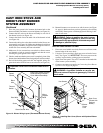
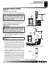
6. Remove all contents from inside stove cavity. Contents include:
(1) - Stove bottom [Amity Only] (Discard - Not used with
this application)
(4) - Legs with leg leveler bolts
(1) - Bottom door
(3) - Top grates
(1) - Hardware kit bag with fasteners
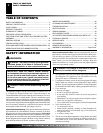
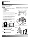
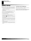
7. Carefully lay stove body on back to attach bottom components to
stove body (see Figure 7). Rest stove on drop cloth or blanket to
avoid scratching stove edges.
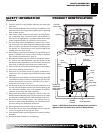
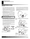
8. Remove remaining pallet wood attached to bottom of stove
body (see Figure 8). Use an adjustable wrench to remove bolts.
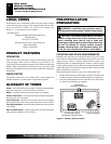
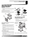
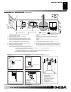
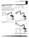
9. Fasten each leg to stove with four (4) M8 x 1.25 - 20mm bolts.
Use a flat washer and lock washer with each bolt. Tighten bolts
into threaded holes on stove body (see Figures 9 and 10). Use
an adjustable wrench or a 12mm and 6mm socket.
10. Attach stove door by inserting step bolt through door hinge pivot
hole and into threaded hole in stove body (Figures 9 and 11). Use
an adjustable wrench or a 12mm socket to fasten step bolt. Tighten
step bolt until snug. Make sure door moves freely.
Figure 10 - Attaching Stove Legs (Oxford™ Model Shown)
Bottom Of
Stove Unit
Leg
Bolt
Washers
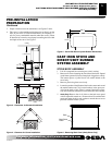
CAST IRON STOVE AND
DIRECT-VENT BURNER
SYSTEM ASSEMBLY
Continued
Figure 7 - Laying Down Stove On Side
Figure 8 - Removing Pallet Wood From The Bottom of The Stove
Pallet
Wood
Bolt
Pallet
Wood
Bottom Of
Stove Unit
Front
Pallet
Wood
Bolted to
Bottom of
Stove Body
Front of
Stove
Unit
Top of Stove Unit
Front of
Stove Unit
Top of
Stove
Unit
Drop
Cloth/
Blanket
Figure 9 - Locating Threaded Holes for Legs and Door Attachment
Door Hinge Step
Bolt Hole
Door Catch Bolt
With Adjustable
Hex Nuts Hole
Leg Hole
Front
Bottom of
Stove Unit
CAST IRON STOVE AND DIRECT-VENT BURNER SYSTEM ASSEMBLY
Stove Body Assembly (Cont.)
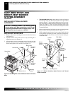
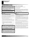
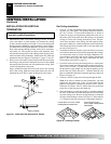
11. Install door catch bolt (M8 x 1.25-55mm with two M8 hex nuts)
into threaded hole on stove body (see Figure 9). Use an adjust-
able wrench or a 12mm socket. The catch bolt has two hex nuts
attached to it (see Figure 12). The top nut is a bolt stop and the
bottom nut is for door leveling adjustment.
Figure 11 - Attaching Stove Door
Step
Bolt
Door Hinge
Threaded
Hole
Stove Door
Bolt Shoulder
Adjusting
Nut
Bolt Stop
Catch
Bolt
Door Claw
Door
Figure 12 - Catch Bolt and
Door Claw Orientation