www.desatech.com
109005-01C4
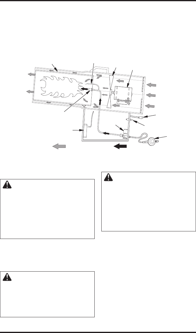
THEORY OF OPERATION
The Fuel System: The hose/regulator assembly attaches to the propane gas supply. The propane gas
moves through the solenoid valve and out the nozzle.
The Air System: The motor turns the fan. The fan pushes air into and around the combustion chamber.
This air is heated and provides a stream of clean, hot air.
The Ignition System: The direct spark ignitor (DSI) sends voltage to the spark plug/ignitor. The spark
plug/ignitor ignites the fuel and air mixture.
The Safety Control System: This system causes the heater to shut down if the flame goes out.
VENTILATION
WARNING: Follow the mini-
mum fresh, outside air ventila-
tion requirements. If proper
fresh, outside air ventilation is
not provided, carbon monoxide
poisoning can occur. Provide
proper fresh, outside air ventila-
tion before running heater.
Provide a fresh air opening of at least 3 ft
2
(0.28 m
2
)
for each 100,000 Btu/Hr rating. Provide extra fresh
air if more heaters are being used.
INSTALLATION
WARNING: Review and un-
derstand the warnings in the
Safety Information section, page
2. They are needed to safely op-
erate this heater. Follow all local
codes when using this heater.
WARNING: Test all gas piping
and connections for leaks after
installation or servicing. Never
use an open flame to check for
a leak. Apply a mixture of liquid
soap and water to all joints.
Bubbles forming show a leak.
Correct all leaks at once.
1. Provide propane supply system (see Propane
Supply, page 3).
2. Connect POL fitting on hose/regulator as
-
sembly to propane tank(s). Turn POL fitting
counterclockwise into threads on tank. Tighten
firmly using wrench. Tighten regulator with vent
pointing over the hose (see Figure 3, page 5).
3. Connect hose to inlet connector. Tighten firmly
using a wrench (see Figure 4, page 5).
IMPORTANT: Extra hose or piping may be
used if needed. Install extra hose or piping
between hose/regulator assembly and propane
tank. You must use the regulator supplied with
heater.
Air For Combustion
And Heating
Fuel
Combustion Chamber
Ignitor
Figure 2 - Cross Section Operational View
Clean
Heated
Air Out
(Front)
Cool
Air In
(Back)
Fan
Motor
Power Cord
Hose/
Regulator
Assembly
Solenoid
Valve
On/Off Switch
DSI
Nozzle


