


12
105986
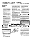
VENT-FREE PROPANE/LP GAS STOVE HEATER
SUN VALLEY STOVE COMPANY
For more information, visit www.desatech.com
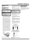
O
N
POSI
T
O
PO
S
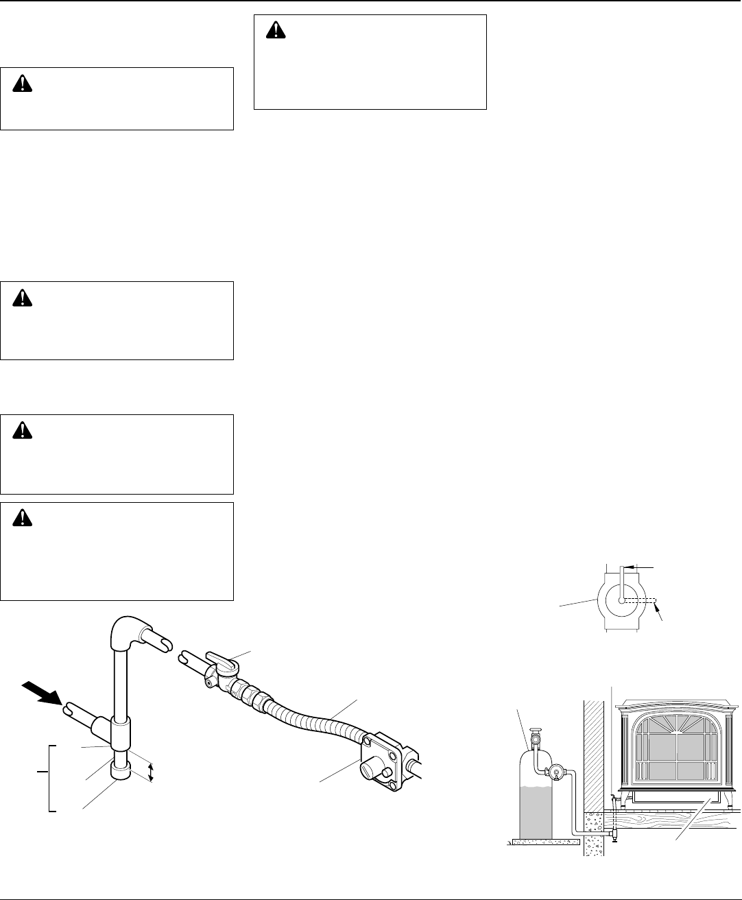
Tee
Joint
Pipe
Nipple
Cap
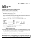
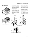
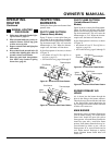
3" Minimum
Sediment
Trap
Gas
Regulator
From External
Regulator (11"
W.C.** to 14"
W.C. Pressure)
CSA/AGA Design-Certified Equipment
Shutoff Valve With 1/8" NPT Tap*
Approved Flexible
Gas Hose (if allowed
by local codes)
Figure 20 - Gas Connection (MSVFBP Series)
* Purchase the optional CSA/AGA design-certified equipment shutoff valve from your
dealer. See Accessories, page 23.
**Minimum inlet pressure for purpose of input adjustment.
CAUTION: Avoid damage to
regulator. Hold gas regulator with
wrench when connecting it to gas
piping and/or fittings.
CAUTION: Use pipe joint seal-
ant that is resistant to liquid pe-
troleum (LP) gas.
Install sediment trap in supply line as shown
in Figure 19, page 11 and Figure 20. Locate
sediment trap where it is within reach for
cleaning. Locate sediment trap where trapped
matter is not likely to freeze. A sediment
trap traps moisture and contaminants. This
keeps them from going into heater controls.
If sediment trap is not installed or is in-
stalled wrong, heater may not run properly.
INSTALLATION
Continued
WARNING: Never use an open
flame to check for a leak. Apply a
mixture of liquid soap and water
to all joints. Bubbles forming show
a leak. Correct all leaks at once.
WARNING: Test all gas pip-
ing and connections for leaks
after installing or servicing. Cor-
rect all leaks at once.
CHECKING GAS
CONNECTIONS
Pressure Testing Gas Supply
Piping System
Test Pressures In Excess Of 1/2 PSIG
(3.5 kPa)
1. Disconnect appliance with its appli-
ance main gas valve (control valve)
and equipment shutoff valve from gas
supply piping system. Pressures in ex-
cess of 1/2 psig will damage heater
regulator.
2. Cap off open end of gas pipe where
equipment shutoff valve was con-
nected.
3. Pressurize supply piping system by ei-
ther using compressed air or opening
propane/LP supply tank valve.
4. Check all joints of gas supply piping
system. Apply mixture of liquid soap
and water to gas joints. Bubbles form-
ing show a leak.
5. Correct all leaks at once.
6. Reconnect heater and equipment
shutoff valve to gas supply. Check re-
connected fittings for leaks.
Test Pressures Equal To or Less Than
1/2 PSIG (3.5 kPa)
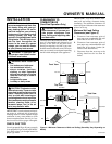
1. Close equipment shutoff valve (see Fig-
ure 21).
2. Pressurize supply piping system by either
using compressed air or opening propane/
LP supply tank valve.
3. Check all joints from gas meter to equip-
ment shutoff valve (see Figure 22). Ap-
ply mixture of liquid soap and water to
gas joints. Bubbles forming show a leak.
4. Correct all leaks at once.
Pressure Testing Heater Gas
Connections
1. Open equipment shutoff valve (see Fig-
ure 21).
2. Open propane/LP supply tank valve.
3. Make sure control knob of heater is in
the OFF position.
4. Check all joints from equipment shutoff
valve to control valve (see Figure 22).
Apply mixture of liquid soap and wa-
ter to gas joints. Bubbles forming show
a leak.
5. Correct all leaks at once.
6. Light heater (see Operating Heater,
pages 14 through 17). Check all other
internal joints for leaks.
7. Turn off heater (see To Turn Off Gas to
Appliance, remote-ready models, page
15, variable manual models, page 16).
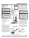
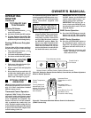
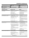
Figure 21- Equipment Shutoff Valve
Closed
Equipment
Shutoff
Valve
Open
Figure 22 - Checking Gas Joints
Control Valve
Location
Propane/LP
Supply Tank
Equipment Shutoff Valve
CAUTION: Make sure exter-
nal regulator has been installed
between propane/LP supply and
heater. See guidelines under
Con-
necting to Gas Supply
, page 11.