


11
105986
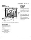
OWNER’S MANUAL
For more information, visit www.desatech.com
CAUTION: Use only new,
black iron or steel pipe. Inter-
nally-tinned copper tubing may
be used in certain areas. Check
your local codes. Use pipe of 1/2"
diameter or greater to allow
proper gas volume to heater. If
pipe is too small, undue loss of
pressure will occur.
Installation must include an equipment shutoff
valve, union, and plugged 1/8" NPT tap.
Locate NPT tap within reach for test gauge
hook up. NPT tap must be upstream from
heater (see Figure 19, MSVFBPR series, or
Figure 20, page 12, MSVFBP series).
IMPORTANT:
Install equipment shutoff
valve in an accessible location. The equip-
ment shutoff valve is for turning on or
shutting off the gas to the appliance.
Apply pipe joint sealant lightly to male
threads. This will prevent excess sealant
from going into pipe. Excess sealant in pipe
could result in clogged heater valves.
WARNING: Never connect
heater to private (non-utility) gas
wells. This gas is commonly
known as wellhead gas.
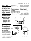
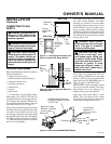
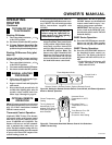
The gas inlet connection for the stove heater
is located on the lower right-hand side of the
stove when viewed from the front of the
unit. The gas connection can be made either
through the bottom right side or through the
lower back opening as illustrated in Figure
17. Make sure gas log heater is secured to
the stove cavity assembly.
INSTALLATION
Continued
CONNECTING TO GAS
SUPPLY
WARNING: A qualified service
person must connect heater to gas
supply. Follow all local codes.
Installation Items Needed
Before installing heater, make sure you have
the items listed below.
• piping (check local codes)
• sealant (resistant to propane/LP gas)
• equipment shutoff valve *
• test gauge connection *
• sediment trap
• tee joint
• pipe wrench
* An CSA/AGA design-certified equip-
ment shutoff valve with 1/8" NPT tap is an
acceptable alternative to test gauge connec-
tion. Purchase the optional CSA/AGA de-
sign-certified equipment shutoff valve from
your dealer. See Accessories, page 23.
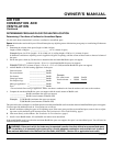
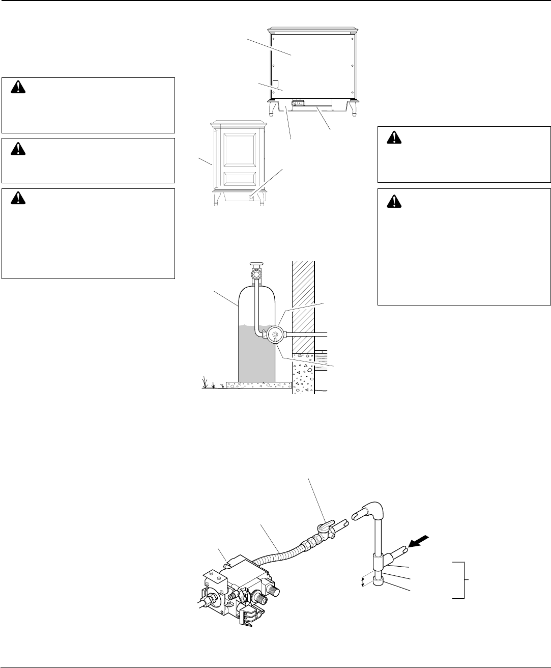
Figure 17 - Gas Regulator Location and
Gas Line Access Into Stove Cabinet
Back Stove
Panel
Front
of
Stove
Unit
Gas Inlet
Connection
Access
Product
Identification
Label
Gas
Log
Heater
Back View
Side View
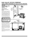
Figure 19 - Gas Connection(MSVFBPR Series)
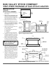
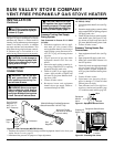
CAUTION: Never connect
heater directly to the propane/LP
supply. This heater requires an
external regulator (not supplied).
Install the external regulator be-
tween the heater and propane/LP
supply.
The installer must supply an external regu-
lator. The external regulator will reduce
incoming gas pressure. You must reduce
incoming gas pressure to between 11 and 14
inches of water. If you do not reduce incom-
ing gas pressure, heater regulator damage
could occur. Install external regulator with
the vent pointing down as shown in Figure
18. Pointing the vent down protects it from
freezing rain or sleet.
Figure 18 - External Regulator With Vent
Pointing Down
Propane/
LP
Supply
Tank
External
Regulator
Vent
Pointing
Down
Continued
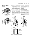
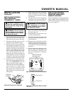
WARNING: This appliance re-
quires a 1/2" NPT (National Pipe
Thread) inlet connection to the
pressure regulator.
3" Minimum
Sediment
Trap
Gas Control
From External
Regulator (11"
W.C.** to 14" W.C.
Pressure)
CSA/AGA Design-Certified
Equipment Shutoff Valve With
1/8" NPT Tap*
Approved Flexible
Gas Hose (if allowed
by local codes)
Tee Joint
Pipe Nipple
Cap