


www.desatech.com
119526-01A 17
INSTALLATION
Continued
Pressure Testing Fireplace Gas
Connections
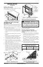
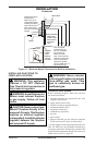
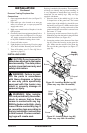
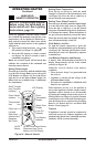
1. Open equipment shutoff valve (see Figure 22,
page 16).
2. Open main gas valve located on or near gas
meter for natural gas or open propane/LP
supply tank valve.
3. Make sure control knob of replace is in the
OFF position.
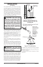
4. Check all joints from equipment shutoff valve
to gas control valve (see Figures 23 or 24, page
16). Apply noncorrosive leak detection uid
to all joints. Bubbles forming show a leak.
5. Correct all leaks at once.
6. Light replace (see Operating Fireplace, page
19.) Check all other internal joints for leaks.
7. Turn off replace (see To Turn Off Gas to
Appliance, page 21).
INSTALLING LOGS
CAUTION: Do not remove the
data plates attached to the heater
base assembly. The data plates
contain important warranty and
safety information.
WARNING: Failure to posi-
tion the parts in accordance
with these diagrams or failure
to use only parts specically
approved with this heater may
result in property damage or
personal injury.
WARNING: After installa-
tion and periodically thereafter,
check to ensure that no ame
comes in contact with any log.
With the heater set to High, check
to see if ame contact any log. If
so, reposition logs according to
the log installation instructions
in this manual. Flames contact-
ing logs will create soot.
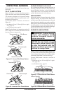
Each log is marked with a number. These numbers
will help you identify the log when installing. It
is very important to install these logs exactly as
instructed. Do not modify logs. Only use logs
supplied with heater.
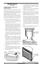
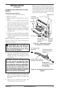
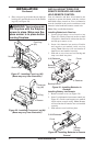
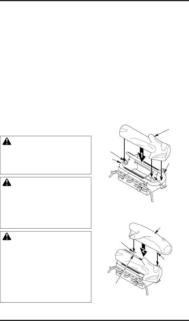
1. Place the base of the middle log (#1) in the
U-shaped slots of the grate base. The cutout
on the right of the middle log should t over
the burner (see Figure 25). Make sure the front
of the middle log is resting on the tabs of the
grate base and the cutout area is centered over
the burner “U” bend.
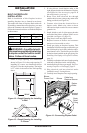
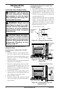
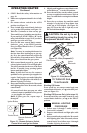
2. Locate pegs on the bottom of back log (#2).
Slide these pegs into the holes in the grate base
behind the burner (see Figure 26).
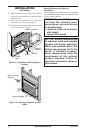
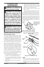
3. Locate the notches in the bottom of the front
log (#3). Place the front log on the grate n-
gers. Make sure the notches of the front log
line up with the grate ngers (see Figure 27,
page 18).
Middle
Log (#1)
Tab
Burner
“U” Bend
U-Shaped
Slot
Figure 25 - Installing Middle Log (#1)
(Base may very from illustration)
Middle
Log (#1)
Figure 26 - Installing Back Log (#2)
(Base may very from illustration)
Hole in
Grate
Base
Back Log (#2)
Peg
Burner