


www.desatech.com
113109-01G 9
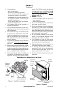
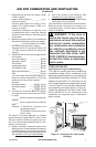
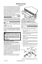
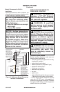
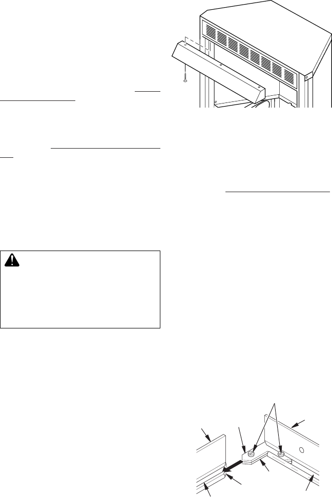
Figure 5 - Installing Hood to Firebox
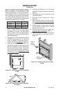
Note: Your replace is designed to be used in
zero clearance installations. Wall or framing ma-
terial can be placed directly against any exterior
surface on the rear, sides or top of your replace,
except where standoff spacers are integrally at-
tached. If standoff spacers are attached to your
replace, these spacers can be placed directly
against wall or framing materials.
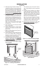
Use the dimensions shown for rough openings
to create the easiest installation. See Built-In
Fireplace Installation, page 12.
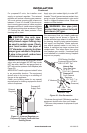
IMPORTANT: Vent-free heaters add moisture
to the air. Although this is benecial, installing
replace in rooms without enough ventilation
air may cause mildew to form from too much
moisture. See Air for Combustion and Ventila-
tion, page 6.
IMPORTANT: Make sure the replace is level.
If replace is not level, log set will not work
properly.
Use the correct gas type (natural or propane/
LP) for your replace. If your gas supply is not
correct, do not install replace. Call dealer
where you bought replace for proper type
replace.
-
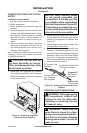
This replace accepts a blower assembly with
an electrical cord. The electrical cord is ve feet
in length. You must locate replace within reach
of a 120 volt grounded electrical outlet. If not,
you must install an electrical outlet within reach
of replace power cord. The GA3555 outlet
accessory is used for built-in applications with
blower accessory installed.
INSTALLING HOOD
Install hood to top of rebox as shown in
Figure 5. Use 3 Phillips screws provided.
INSTALLATION
Continued
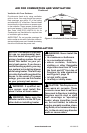
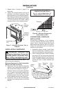
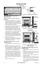
Figure 6 - Assembling Perimeter Trim
Side Trim
Top
Trim
Slot
Mitered
Edge
Slot
Shim
Set Screws
Adjusting
Plate
ASSEMBLING AND ATTACHING
OPTIONAL PERIMETER TRIM
IMPORTANT: If you are recessing the re-
box in a wall, do not attach perimeter trim at
this time. See Built-In Fireplace Installation,
page 12.
Note: The instructions below show assembling
and attaching perimeter trim to replace.
1. Remove packaging from three pieces of
perimeter trim.
2. Locate four perimeter screws, two adjust-
ing plates with set screws and two shims
in the hardware packet.
3. Align shim under adjusting plate as shown
in Figure 6.
4. Slide one end of adjusting plate/shim in
slot on mitered edge of top perimeter trim
(see Figure 6).
5. Slide other end of adjusting plate/shim in
slot on mitered edge of side perimeter trim
(see Figure 6).
6. While rmly holding edges of perimeter trim
together, tighten both set screws on the
adjusting plate with slotted screwdriver.