


www.desatech.com
119426-01A16
CHECKING GAS CONNECTIONS
WARNING: Test all gas piping
and connections, internal and
external to unit, for leaks after
installing or servicing. Correct
all leaks at once.
WARNING: Never use an
open ame to check for a leak.
Apply a noncorrosive leak detec-
tion uid to all joints. Bubbles
forming show a leak. Correct all
leaks at once.
CAUTION: Make sure exter-
nal regulator has been installed
between propane/LP supply
and heater. See guidelines un-
der Connecting to Gas Supply,
page 14.
PRESSURE TESTING GAS SUPPLY
PIPING SYSTEM
Test Pressures In Excess Of 1/2 PSIG
(3.5 kPa)
1. Disconnect appliance with its appliance main
gas valve (control valve) and equipment
shutoff valve from gas supply piping system.
Pressures in excess of 1/2 psig will damage
heater regulator.
2. Cap off open end of gas pipe where equipment
shutoff valve was connected.
3. Pressurize supply piping system by either
opening propane/LP supply tank valve for
propane/LP gas or opening main gas valve
located on or near gas meter for natural gas
or using compressed air.
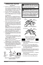
4. Check all joints of gas supply piping system.
Apply noncorrosive leak detection uid to all
joints. Bubbles forming show a leak.
5. Correct all leaks at once.
6. Reconnect heater and equipment shutoff valve
to gas supply. Check reconnected ttings for
leaks.
Test Pressures Equal To or Less Than 1/2
PSIG (3.5 kPa)
1.
Close equipment shutoff valve (see Figure 17).
2. Pressurize supply piping system by either
opening propane/LP supply tank valve for
propane/LP gas or opening main gas valve
located on or near gas meter for natural gas
or using compressed air.
3. Check all joints from gas meter to equipment
shutoff valve for natural gas or propane/LP
supply to equipment shutoff valve for pro-
pane/LP (see Figure 18 or 19, page 17). Apply
noncorrosive leak detection uid to all joints.
Bubbles forming show a leak.
4. Correct all leaks at once.
PRESSURE TESTING HEATER GAS
CONNECTIONS
1.
Open equipment shutoff valve (see Figure 17).
2. Open main gas valve located on or near gas
meter for natural gas or open propane/LP
supply tank valve.
3. Make sure control knob of heater is in the OFF
position.
4. Check all joints from equipment shutoff valve
to thermostat gas valve (Thermostat-Con-
trolled Models) or to gas control (Remote-
Ready Models) (see Figure 18 or 19, page
17). Apply noncorrosive leak detection uid
to all joints. Bubbles forming show a leak.
5. Correct all leaks at once.
6. Light heater (see Operating Heater, page 20
or 22, depending on your model). Check all
other internal joints for leaks.
7.
Turn off heater (see To Turn Off Gas to Appli-
ance, page 21 for Thermostat-Controlled mod-
els or page 23 for Remote-Ready Models).
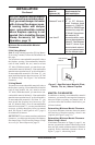
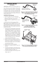
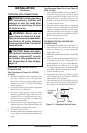
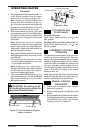
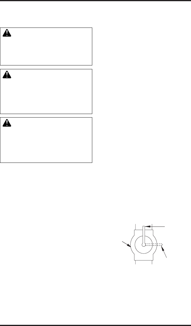
Figure 17 - Equipment Shutoff Valve
Open
Closed
Equipment
Shutoff
Valve
INSTALLATION
Continued