


www.desatech.com
119421-01A 15
INSTALLATION
Continued
Test Pressures Equal To or Less Than
1/2 PSIG (3.5 kPa)
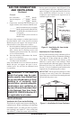
1. Close equipment shutoff valve (see Figure 15).
2. Pressurize supply piping system by either
opening propane/LP supply tank valve for
propane/LP gas or opening main gas valve
located on or near gas meter for natural gas
or using compressed air.
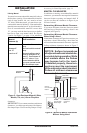
3. Check all joints from gas meter to equipment
shutoff valve for natural gas or propane/LP
supply to equipment shutoff valve for pro-
pane/LP (see Figures 16 and 17). Apply
noncorrosive leak detection uid to all joints.
Bubbles forming show a leak.
4. Correct all leaks at once.
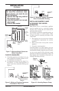
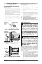
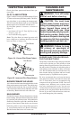
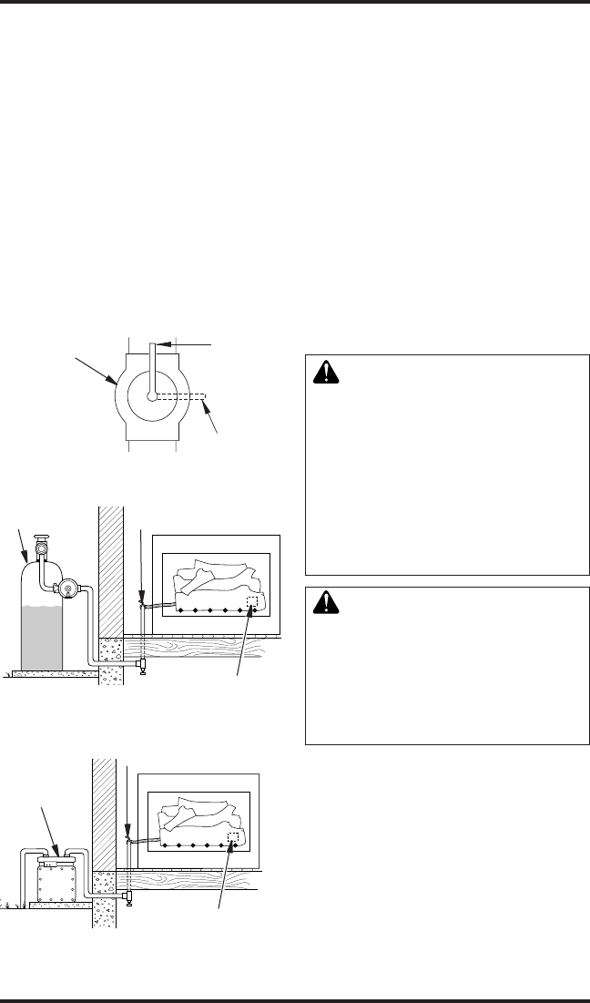
Figure 15 - Equipment Shutoff Valve
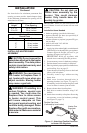
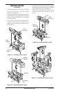
Figure 16 - Checking Gas Joints
(Propane/LP Gas Models)
Equipment
Shutoff Valve
Propane/LP
Supply Tank
Control Valve Location
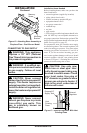
Figure 17 - Checking Gas Joints (Natural
Gas Models)
Gas Meter
Equipment Shutoff Valve
Control Valve Location
Equipment
Shutoff
Valve
Open
Closed
pRESSURE TESTING HEATER GAS
CONNECTIONS
1. Open equipment shutoff valve (see Figure 15).
2. Open main gas valve located on or near gas
meter for natural gas or open propane/LP
supply tank valve.
3. Make sure control knob of heater is in the OFF
position.
4. Check all joints from equipment shutoff valve
to control valve (see Figures 16 and 17). Apply
noncorrosive leak detection uid to all joints.
Bubbles forming show a leak.
5. Correct all leaks at once.
6. Light heater (see Operating Heater, page 17).
Check all other internal joints for leaks.
7. Turn off heater (see To Turn Off Gas to Appli-
ance, page 18).
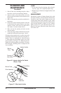
INSTALLING LOGS
CAUTION: After installa-
tion and periodically thereafter,
check to ensure that no ame
comes in contact with any log.
With the heater set to HI, check
to see if ames contact any log. If
so, reposition logs according to
the log installation instructions
in this manual. Flames contact-
ing logs will create soot.
WARNING: Failure to posi-
tion the parts in accordance
with these diagrams or failure
to use only parts specically
approved with this heater may
result in property damage or
personal injury.
Each log is marked with a number. These numbers
will help you identify the log when installing. It
is very important to install these logs exactly as
instructed. Do not modify logs. Only use logs
supplied with heater.
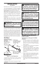
1. Place front log (#1) on grate ngers. Make sure
front log rests rmly between grate ngers and
grate base (see Figure 18, page 16).
2. Place base of middle log (#2) in U-shaped
slots of grate base. The large cutout on bottom
right of middle log should t over burner (see
Figure 19, page 16). Make sure front of middle
log is resting on tabs of grate base.