


www.desatech.com
113195-01C14
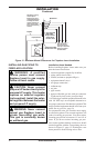
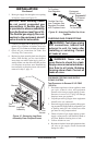
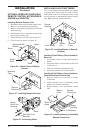
3. Route gas supply line through access opening
of replace insert (see Figure 15).
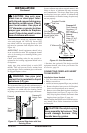
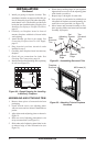
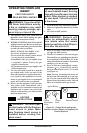
NOTICE: Most building codes
do not permit concealed gas
connections. A exible gas line
is provided to allow accessibility
from the replace (see Figure 16).
The exible gas supply line con-
nection to the equipment shutoff
valve should be accessible.
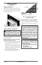
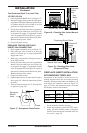
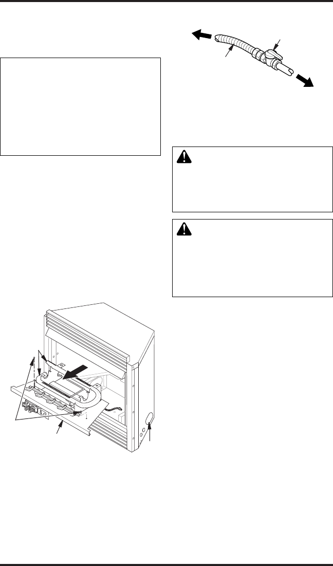
4. Connect gas supply line to exible gas line at-
tached to gas regulator of replace insert (see
Figure 16). Use sealant on all male pipe threads.
5. Check all gas connections for leaks. See
Checking Gas Connections.
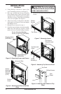
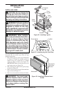
6. Replace log base assembly back into replace
insert. Feed exible gas line into replace
insert base area while replacing log base as-
sembly. Make sure the entire exible gas line
is in replace insert base area. Reattach log
base assembly to replace insert with screws
removed in step 2, page 13.
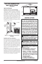
Figure 15 - Removing Log Base
Assembly From Fireplace Insert
Burners
Log Base
Assembly
Gas
Line
Access
INSTALLATION
Continued
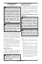
Figure 16 - Attaching Flexible Gas Lines
Together
Flexible Gas Line
from Fireplace Gas
Regulator Provided
with Fireplace Insert
To Fireplace
Gas Regulator
Equipment
Shutoff Valve
Propane/LP
To External
Regulator
Natural
To Gas Meter
CHECKING GAS CONNECTIONS
WARNING: Test all gas piping
and connections, internal and
external to unit, for leaks after
installing or servicing. Correct
all leaks at once.
WARNING: Never use an
open ame to check for a leak.
Apply a noncorrosive leak detec-
tion uid to all joints. Bubbles
forming show a leak. Correct all
leaks at once.
PRESSURE TESTING GAS SUPPLY
PIPING SYSTEM
Test Pressures In Excess Of 1/2 PSIG
(3.5 kPa)
1. Disconnect appliance with its appliance main
gas valve (control valve) and equipment
shutoff valve from gas supply piping system.
Pressures in excess of 1/2 psig will damage
replace insert gas regulator.
2. Cap off open end of gas pipe where equipment
shutoff valve was connected.
3. Pressurize supply piping system by either open-
ing propane/LP supply tank for propane/LP gas
or opening main gas valve located on or near
gas meter or using compressed air.
4. Check all joints of gas supply piping system.
Apply a noncorrosive leak detection uid to
all joints. Bubbles forming show a leak.
5. Correct all leaks at once.
6. Reconnect replace insert and equipment shut-
off valve to gas supply. Check reconnected
ttings for leaks.
Two
Screws