


www.desatech.com
108382-01G 13
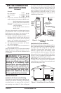
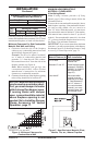
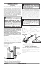
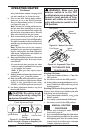
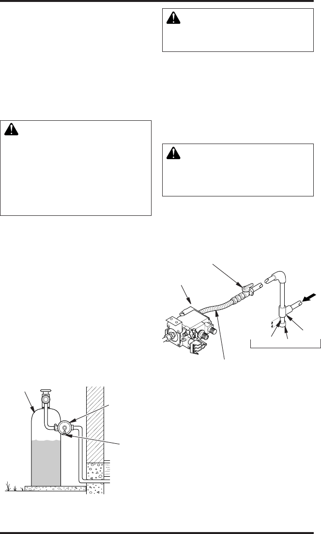
For propane/LP units, the installer must supply
an external regulator. The external regulator will
reduce incoming gas pressure. You must reduce
incoming gas pressure to between 11" and 14" of
water. If you do not reduce incoming gas pres-
sure, heater regulator damage could occur. Install
external regulator with the vent pointing down
as shown in Figure 13. Pointing the vent down
protects it from freezing rain or sleet.
-
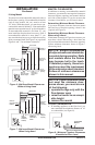
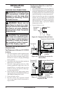
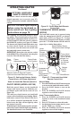
Installation must include an equipment shutoff valve,
union, and plugged 1/8" NPT tap. Locate NPT tap
within reach for test gauge hook up. NPT tap must
be upstream from heater (see Figure 14).
IMPORTANT: Install equipment shutoff valve
in an accessible location. The equipment shutoff
valve is for turning on or shutting off the gas to
the appliance.
Check your building codes for any special re-
quirements for locating equipment shutoff valve
to replaces.
Apply pipe joint sealant lightly to male NPT
threads. This will prevent excess sealant from
going into pipe. Excess sealant in pipe could result
in clogged heater valves.
INSTALLATION
Continued
Figure 13 - External Regulator With Vent
Pointing Down (propane/LP gas only)
Propane/LP
Supply Tank
External
Regulator
Vent
Pointing
Down
* Purchase the optional CSA design-certified
equipment shutoff valve from your dealer. See
Accessories, page 25.
** Minimum inlet pressure for purpose of input
adjustment.
Figure 14 - Gas Connection
Gas Control
3" Minimum
CSA Design-
Certied
Equipment Shutoff
Valve With 1/8"
NPT Tap*
Approved Flexible Gas Hose
(if allowed by local codes)
Pipe Tee
Nipple Cap Joint
Sediment Trap
Natural Gas
From Gas Meter
(5" W.C.** to 10.5" W.C.
Pressure)
From External Regulator
(11" W.C.** to 14" W.C.
Pressure)
We recommend that you install sediment trap in
supply line as shown in Figure 14. Locate sediment
trap where it is within reach for cleaning. Install
in piping system between fuel supply and heater.
Locate sediment trap where trapped matter is not
likely to freeze. A sediment trap traps moisture and
contaminants. This keeps them from going into
heater controls. If sediment trap is not installed or
is installed wrong, heater may not run properly.