


23
104385
OWNER’S MANUAL
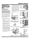
OPTIONAL POSI-
TIONING OF THER-
MOSTAT SENSING
BULB
For Masonry and Factory-
built Metal Fireplace
If your log set cycles to pilot, but the
room temperature drops to a lower
than ideal comfort level before the log
set comes back on, you may want to
reposition the thermostat sensing bulb.
The thermostat sensing bulb is located near
the gas valve assembly on the mounting
bracket. This location allows the thermostat
to keep the room temperature at an ideal
comfort level for most fireplace applica-
tions. For positioning the thermostat sens-
ing bulb elsewhere, an adhesive-backed
mounting clip is available.
Tools needed: 1/4" hex driver or socket
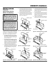
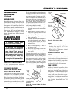
1. Remove logs. Locate the gas valve as-
sembly and thermostat sensing bulb
(see Figure 38).
2. With 1/4" hex driver or socket, loosen
the thermostat screw. Carefully slide
the thermostat sensing bulb out of the
retaining clamp (see Figure 40).
Note:
Do not remove the screw. Make
sure you tighten the screw after remov-
ing the thermostat sensing bulb.
IMPORTANT:
Do not force or bend the
thermostat sensing bulb or capillary.
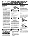
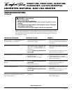
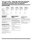
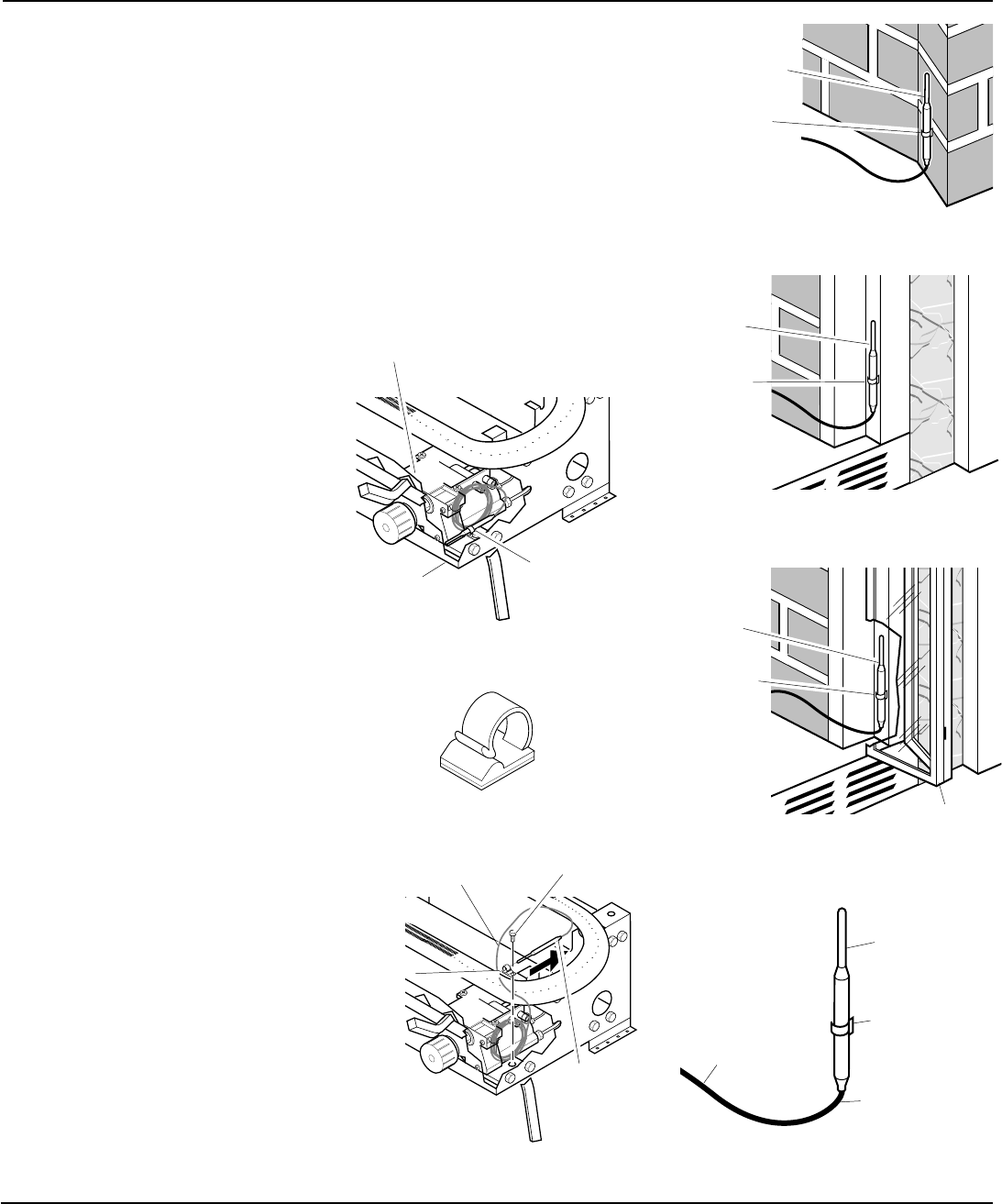
3. The thermostat sensing bulb may be
located to the lower right front side of
fireplace. Determine location of sens-
ing bulb, but do not mount sensing bulb
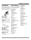
until step 5. If you have a masonry fire-
place, see Figure 41 for location. If you
have a factory-built metal fireplace, see
Figure 42 for location. If your fireplace
has glass doors, position sensing bulb
directly behind door gap on right bot-
tom side (see Figure 43).
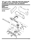
4. The mounting clip must be a minimum
of 3" from bottom of fireplace to pre-
vent crimping of capillary. Once you
have decided on a location, clean the
area thoroughly. Remove the paper
backing from the adhesive on back of
mounting clip. Press the clip into the
new location so that the thermostat
sensing bulb will be positioned verti-
cally with the capillary at the bottom
(see Figure 44). Slide the thermostat
sensing bulb into the clip.
IMPORTANT:
Do not crimp capillary.
Thermostat
Sensing Bulb
Figure 38 - Location of Gas Valve Assem-
bly and Thermostat Sensing Bulb
Figure 39 - Adhesive-backed Mounting
Clip
Figure 40 - Removing Thermostat Sens-
ing Bulb
Gas Valve
Assembly
Mounting
Bracket
Thermostat Screw
Retaining
Clamp
Thermostat
Sensing Bulb
Capillary
Adhesive-
backed
Mounting Clip
Figure 41 - Locating Thermostat Sensing
Bulb on Masonry Fireplace
Thermostat
Sensing Bulb
Adhesive-
backed
Mounting
Clip
Thermostat
Sensing
Bulb
Figure 42 - Locating Thermostat Sensing
Bulb on Factory-built Metal Fireplace
Adhesive-
backed
Mounting
Clip
Glass Doors
Figure 43 - Installing Thermostat Sensing
Bulb behind Glass Doors
Thermostat
Sensing
Bulb
Capillary
Thermostat
Sensing Bulb
Do Not Crimp
Capillary
Adhesive-
backed
Mounting
Clip
Figure 44 - Positioning the Thermostat
Sensing Bulb in the Vertical Position with
the Capillary at the Bottom