


10
104385
UNVENTED NATURAL GAS LOG HEATER
CGS2718N, CGS3124N, CLD3018N,
CLD3924NT, and CCL3930NT(A)
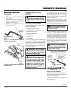
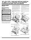
INSTALLING HEATER BASE
ASSEMBLY
IMPORTANT:
Make sure the heater burners
are level. If heater is not level, heater will not
work properly. For thermostat models, avoid
damage to thermostat bulb. Avoid nicks or
sharp bends in thermostat bulb wire. Keep
thermostat bulb in mounting bracket.
WARNING: If installing in a
sunken fireplace, special care is
needed. You must raise the fire-
place floor to allow access to
heater control panel. This will in-
sure adequate air flow and guard
against sooting. Raise fireplace
floor with noncombustible mate-
rial. Make sure material is secure.
CAUTION: Do not pick up
heater base assembly by the
burner. This could damage
heater. Only handle base assem-
bly by grates.
WARNING: You must secure
this heater to fireplace floor. If
not, heater will move when you
adjust controls. Moving heater
may cause a gas leak.
INSTALLATION
Continued
INSTALLING DAMPER
CLAMP ACCESSORY FOR
VENTED OPERATION
Note:
When used as a vented heater, appli-
ance must be installed only in a solid-fuel
burning fireplace with a working flue and
constructed of noncombustible material.
If your heater is a manually controlled model,
you may use this heater as a vented product.
There are three reasons for operating your
heater in the vented mode.
1. The fireplace does not meet the clear-
ance to combustibles requirements for
vent-free operation.
2. State or local codes do not permit vent-
free operation.
3. You prefer vented operation.
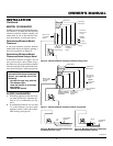
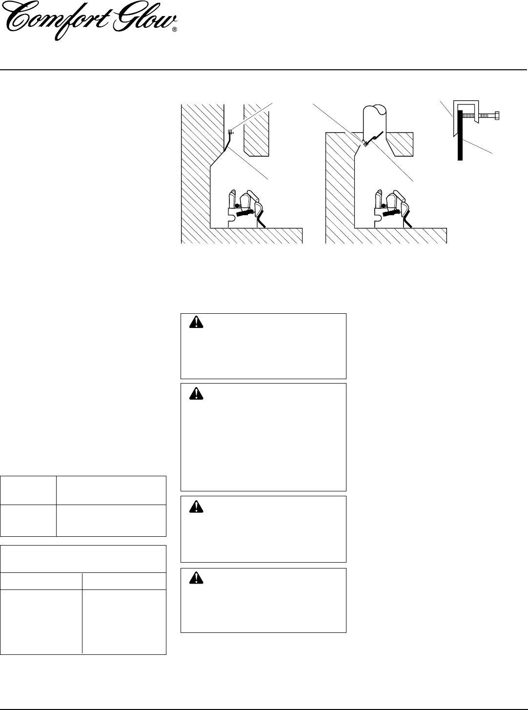
If reasons number 1 or 2 above apply to you,
you must permanently open chimney flue
damper. You must install the damper clamp
accessory (to order, see Accessories, page
25). This will insure vented operation (see
Figure 10). The damper clamp will keep
damper open. Installation instructions are
included with clamp accessory.
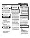
See chart below for minimum permanent
flue opening you must provide. Attach
damper clamp so the minimum permanent
flue opening will be maintained at all times.
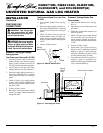
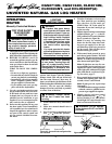
Figure 10 - Attaching Damper Clamp
Damper
Clamp
Damper
Chimney Minimum Permanent
Height (ft.) Flue Opening (sq. ins.)
6' to 15' 39 sq. inches
15' to 30' 29 sq. inches
Area of Various Standard
Round Flues
Diameter (ins.) Area (sq. ins.)
5" 20 sq. inches
6" 29 sq. inches
7" 39 sq. inches
8" 51 sq. inches
Installation Items Needed
• hardware package (provided with heater)
• approved flexible gas hose (not provided)
(if allowed by local codes)
• sealant (resistant to propane/LP gas, not
provided)
• electric drill with 3/16" drill bit
1. Apply pipe joint sealant lightly to male
threads of the fitting to be threaded into
gas regulator. Connect approved flex-
ible gas hose to gas regulator of heater
(see Figure 11, page 12).
IMPORTANT:
Hold gas regulator with
wrench when connecting flexible gas
hose.
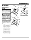
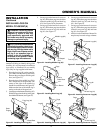
2. Locate masonary screws in hardware
package.
3. Position heater base assembly in fireplace.
4. Mark screw locations through holes in
mounting brackets (see Figure 12, page
12). If installing in a brick-bottom fire-
place, mark screw locations in mortar
joint of bricks.
5. Remove heater base from fireplace.
Damper
Damper
Clamp
Damper
Manufactured FireplaceMasonry Fireplace
CAUTION: Do not remove the
metal Data Plates attached to the
heater base assembly. The Data
Plates contain important warranty
information.