


10
103413
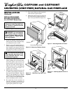
UNVENTED (VENT-FREE) NATURAL GAS FIREPLACE
CGFP28N and CGFP28NT
INSTALLATION
Continued
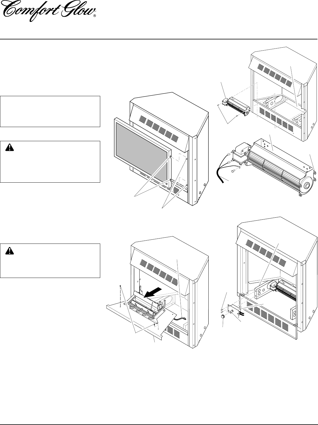
INSTALLING GA3650T
BLOWER ACCESSORY
(For CGFP28PT Model Only)
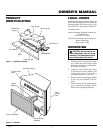
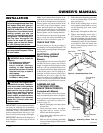
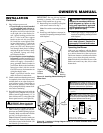
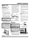
1. Remove fireplace screen (see Figure 15).
NOTICE: Shut-off gas supply and
disconnect heater from gas sup-
ply. Contact a qualified service
person to do this.
CAUTION: Do not pick up log
base assembly by burners. This
could damage burners. Only
handle base by grates.
Figure 15 - Removing Fireplace Screen
Notches
Screen Mounting Screws
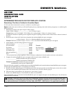
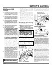
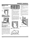
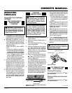
Figure 18 - Attaching Speed Control to
Firebox
Screws
Speed
Control
Control
Knob
Left Floor
Support
Bracket
Control
Shaft
Figure 17 - Mounting Blower to Firebox
Blower
Screws
Lower
Rear Wall
of Firebox
Exhaust Port
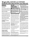
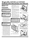
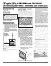
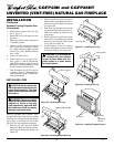
Figure 16 - Removing Log Base from
Fireplace
Screws
Log Base
Flexible
Gas Line
WARNING: You must operate
this fireplace with the fireplace
screen in place. Make sure fire-
place screen is in place before
running fireplace.
2. If logs are installed, carefully remove
the logs and set aside, noting the prop-
erly mounted location of each.
3. Remove screws that attach log base as-
sembly to fireplace. Carefully lift up log
base assembly and remove from fire-
place, taking care to pull flexible gas line
through the access holes (see Figure 16).
4. Attach power cord to blower motor by
firmly pushing the two female termi-
nals of the power cord onto the two
spade terminals on blower motor. Us-
ing screw provided, attach ringed ter-
minal of power cord to mounting tab
of blower housing (see Figure 17).
Tighten screw securely.
5. Place the blower against lower rear wall
of firebox outer wrapper with the ex-
haust port directed upward. Align the
holes in top mounting tabs of blower
with holes in wall of wrapper (see Fig-
ure 17). Using 2 screws provided, mount
blower and tighten screws securely.
6. Be certain that all wire terminals are
securely attached to terminals on
blower motor and that the screw retain-
ing the green ground wire is tight.
7. Place control knob provided on plastic
control shaft of speed control.
8. Mount the speed control on the front
leg of the left floor support bracket us-
ing 2 screws provided (see Figure 18).
Power Cord