


13
107123
OWNER’S MANUAL
For more information, visit www.desatech.com
WARNING: Never use an open
flame to check for a leak. Apply a
mixture of liquid soap and water
to all joints. Bubbles forming
show a leak. Correct all leaks at
once.
WARNING: Test all gas pip-
ing and connections for leaks
after installing or servicing. Cor-
rect all leaks at once.
CHECKING GAS
CONNECTIONS
Continued
Pressure Testing Gas Supply
Piping system
Test Pressures In Excess Of 1/2 PSIG
(3.5 kPa)
1. Disconnect appliance with its appliance
main gas valve (control valve) and equip-
ment shutoff valve from gas supply pip-
ing system. Pressures in excess of 1/2 psig
will damage heater regulator.
2. Cap off open end of gas pipe where
equipment shutoff valve was con-
nected.
3. Pressurize supply piping system by ei-
ther using compressed air or opening
main gas valve located on or near gas
meter.
4. Check all joints of gas supply piping
system. Apply mixture of liquid soap
and water to gas joints. Bubbles form-
ing show a leak.
5. Correct all leaks at once.
6. Reconnect heater and equipment
shutoff valve to gas supply. Check re-
connected fittings for leaks.
INSTALLATION
Continued
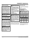
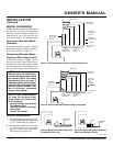
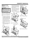
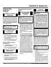
Figure 16 - Equipment Shutoff Valve
ON
POSITION
OFF
POSITION
Open
Closed
Equipment
Shutoff Valve
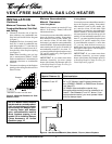
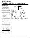
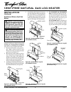
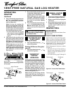
Figure 17 - Checking Gas Joints
Gas Meter
Equipment
Shutoff
Valve
Thermostat Gas Valve or
Control Valve Location
Test Pressures Equal To or Less Than
1/2 PSIG (3.5 kPa)
1. Close equipment shutoff valve (see Fig-
ure 16).
2. Pressurize supply piping system by ei-
ther using compressed air or opening
main gas valve located on or near gas
meter.
3. Check all joints from gas meter to
equipment shutoff valve (see Figure
17). Apply mixture of liquid soap and
water to gas joints. Bubbles forming
show a leak.
4. Correct all leaks at once.
Pressure Testing Heater Gas
Connections
1. Open equipment shutoff valve (see Fig-
ure 16).
2. Open main gas valve located on or near
gas meter.
3. Make sure control knob of heater is in
the OFF position.
4. Check all joints from equipment shutoff
valve to control valve (see Figure 17).
Apply mixture of liquid soap and wa-
ter to gas joints. Bubbles forming show
a leak.
5. Correct all leaks at once.
6. Light heater (see Operating Heater,
pages 18 and 19 [manually-controlled
models] or pages 19 and 20 [thermo-
statically-controlled models]). Check
all other internal joints for leaks.
7. Turn off heater (see To Turn Off Gas to
Appliance, page 19 [manually-con-
trolled models] or page 20 [thermostati-
cally-controlled models]).