


107123-01F
For more information, visit www.desatech.com
For more information, visit www.desatech.com
20
OPERATING HEATER (THERMOSTATICALLY-CONTROLLED MODELS)
Thermostat Control Operation
Manual Lighting Procedure
INSPECTING BURNERS
CLEANING AND MAINTENANCE
OPERATING HEATER
Continued
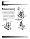
1. Follow steps 1 through 5 under Lighting Instructions, page 19.
2. Depress control knob and light pilot with match.
3. Keep control knob pressed in for 30 seconds after lighting
pilot. After 30 seconds, release control knob. Now follow
step 8 under Lighting Instructions, page 19.
THERMOSTAT
CONTROL OPERATION
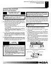
The thermostat control knob can be set to any comfort level
between HI and LO. The thermostat will gradually modulate
the heat output and flame height from higher to lower settings,
or pilot, in order to maintain the comfort level you select. The
ideal comfort setting will vary by household depending upon the
amount of space to be heated, the output of the central heating
system, etc.
Note:
Selecting the HI setting with the control knob will cause
the burners to remain fully on, without modulating down in
most cases.
MANUAL LIGHTING
PROCEDURE
INSPECTING BURNERS
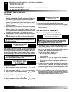
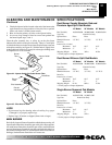
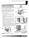
Check pilot flame pattern and burner flame patterns often.
PILOT FLAME PATTERN
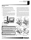
Figure 42 shows a correct pilot flame pattern. Figure 43 shows an
incorrect pilot flame pattern. The incorrect pilot flame is not
touching the thermocouple. This will cause the thermocouple to
cool. When the thermocouple cools, the heater will shut down.
If pilot flame pattern is incorrect, as shown in Figure 44
• turn heater off (see To Turn Off Gas to Appliance, page 18 for
manually-controlled models or page 19 for thermostat-controlled
models)
• see Troubleshooting, pages 22 through 24
Note:
The pilot flame on natural gas units will have a slight curve,
but flame should be blue and have no yellow or orange color.
Figure 42 - Correct Pilot
Flame Pattern
Figure 43 - Incorrect Pilot
Flame Pattern
Thermocouple
Pilot Burner
Thermocouple
Pilot Burner
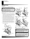
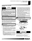
BURNER PRIMARY AIR HOLES
Air is drawn into the burner through the holes in the fitting at the
entrance to the burner. These holes may become blocked with dust
or lint. Periodically inspect these holes for any blockage and clean
as necessary. Blocked air holes will create soot.
MAIN BURNER
Periodically inspect all burner flame holes with the heater running. All
slotted burner flame holes should be open with yellow flame present.
All round burner flame holes should be open with a small blue flame
present. Some burner flame holes may become blocked by debris or
rust, with no flame present. If so, turn off heater and let cool, Remove
blockage, blocked burner flame holes will create soot.
CLEANING AND MAINTENANCE
WARNING: Turn off heater and let cool before
cleaning.
CAUTION: You must keep control areas, burner,
and circulating air passageways of heater clean. In-
spect these areas of heater before each use. Have
heater inspected yearly by a qualified service person.
Heater may need more frequent cleaning due to exces-
sive lint from carpeting, bedding material, pet hair, etc.
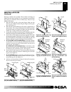
CLEANING BURNER INJECTOR HOLDER
AND PILOT AIR INLET HOLE
The primary air inlet holes allow the proper amount of air to mix with
the gas. This provides a clean burning flame. Keep these holes clear of
dust, dirt, lint, and pet hair. Clean these air inlet holes prior to each
heating season. Blocked air holes will create soot. We recommend that
you clean the unit every three months during operation and have heater
inspected yearly by a qualified service person.
We also recommend that you keep the burner tube and pilot assembly
clean and free of dust and dirt. To clean these parts we recommend
using compressed air no greater than 30 PSI. Your local computer
store, hardware store, or home center may carry compressed air in a
can. You can use a vacuum cleaner in the blow position. If using
compressed air in a can, please follow the directions on the can. If you
don't follow directions on the can, you could damage the pilot
assembly.
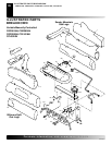
1. Shut off the unit, including the pilot. Allow the unit to cool for
at least thirty minutes.
2. Inspect burner, pilot, and primary air inlet holes on injector
holder for dust and dirt (see Figure 44, page 21).
3. Blow air through the ports/slots and holes in the burner.