


13
104326
OWNER’S MANUAL
O
POSI
P
O
Pressure Testing Gas Supply
Piping System
Test Pressures In Excess Of 1/2 PSIG
1. Disconnect fireplace and its individual
manual shutoff valve from gas supply
piping system. Pressures in excess of
1/2 psig will damage fireplace regulator.
2. Cap off open end of gas pipe where
manual shutoff valve was connected.
3. Pressurize supply piping system by ei-
ther using compressed air or opening
main gas valve located on or near gas
meter.
4. Check all joints of gas supply piping
system. Apply mixture of liquid soap
and water to gas joints. Bubbles form-
ing show a leak.
5. Correct all leaks at once.
Test Pressures Equal To or Less Than
1/2 PSIG
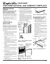
1. Close manual shutoff valve (see
Figure 19).
2. Pressurize supply piping system by ei-
ther using compressed air or opening
main gas valve located on or near gas
meter.
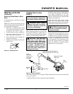
3. Check all joints from gas meter to
manual shutoff valve (see Figure 20).
Apply mixture of liquid soap and wa-
ter to gas joints. Bubbles forming
show a leak.
4. Correct all leaks at once.
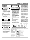
Open
Closed
Manual
Shutoff
Valve
CHECKING GAS
CONNECTIONS
Figure 19 - Manual Shutoff Valve
Gas Meter
Figure 20 - Checking Gas Joints
Manual
Shutoff
Valve
WARNING: Test all gas pip-
ing and connections for leaks
after installing or servicing. Cor-
rect all leaks at once.
WARNING: Never use an open
flame to check for a leak. Apply a
mixture of liquid soap and water
to all joints. Bubbles forming show
a leak. Correct all leaks at once.
Pressure Testing Fireplace Gas
Connections
1. Open manual shutoff valve (see Fig-
ure 19).
2. Open main gas valve located on or near
gas meter.
3. Make sure control knob of fireplace is
in the OFF position.
4. Check all joints from manual shutoff
valve to thermostat gas valve (see Fig-
ure 20). Apply mixture of liquid soap
and water to gas joints. Bubbles form-
ing show a leak.
5. Correct all leaks at once.
6. Light fireplace (see Operating Fire-
place, pages 14 and 15). Check all other
internal joints for leaks.
7. Turn off fireplace (see To Turn Off Gas
to Appliance, page 15).
8. Replace front panel.
INSTALLATION
Continued
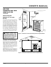
INSTALLING 9-VOLT
BATTERY FOR WIRELESS
REMOTE CONTROL
Two 9-volt batteries (not included) are re-
quired to operate this heater with the wire-
less hand held remote control set. One bat-
tery must be installed in the receiver and one
in the hand-held remote control unit.
Note:
Only use alkaline batteries.
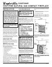
Installing 9-Volt Battery in Hand-
Held Remote Control Unit
1. Remove battery cover on back of re-
mote control unit.
2. Attach terminal wires to the battery.
Place battery into the battery housing.
3. Replace battery cover onto remote con-
trol unit.
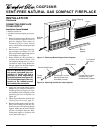
Installing 9-Volt Battery in
Receiver
1. Locate back of receiver located at the
bottom, left side of the heater base.
2. Locate the battery clip mounted on the
back of the receiver.
3. Slide a 9-volt battery through the clip.
4. Attach the terminal wires to the battery.
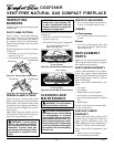
Figure 21 - Attaching Battery to Receiver
Battery Clip
9-Volt Battery
Receiver
Terminal
Wires
Battery Cover
9-Volt Battery
Terminal
Wires
Figure 22 - Installing Battery in Hand-
Held Remote Control Unit
Remote Control Unit
Battery Housing