


11
104326
OWNER’S MANUAL
CONNECTING TO GAS
SUPPLY
NOTICE: A qualified service per-
son must connect fireplace to
gas supply. Follow all local codes.
IMPORTANT:
Check gas line pressure
before connecting fireplace to gas line. Gas
line pressure must be no greater than 14
inches of water. If gas line pressure is higher,
fireplace regulator damage could occur.
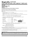
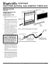
Installation must include a manual shutoff
valve, union, and plugged 1/8" NPT tap.
Locate NPT tap within reach for test gauge
hook up. NPT tap must be upstream from
fireplace (see Figure 16).
Apply pipe joint sealant lightly to male
threads. This will prevent excess sealant
from going into pipe. Excess sealant in pipe
could result in clogged fireplace valves.
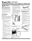
Install sediment trap in supply line as shown
in Figure 16. Locate sediment trap where it
is within reach for cleaning. Locate sedi-
ment trap where trapped matter is not likely
to freeze. A sediment trap traps moisture
and contaminants. This keeps them from
going into fireplace controls. If sediment
trap is not installed or is installed wrong,
fireplace may not run properly.
WARNING: Never connect
fireplace to private (non-utility)
gas wells. This gas is commonly
known as wellhead gas.
CAUTION : Use only new,
black iron or steel pipe. Inter-
nally-tinned copper tubing may
be used in certain areas. Check
your local codes. Use pipe of 1/2"
or greater diameter to allow
proper gas volume to fireplace. If
pipe is too small, undue loss of
pressure will occur.
CAUTION: Use pipe joint seal-
ant that is resistant to liquid pe-
troleum (LP) gas.
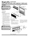
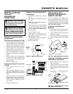
Attaching Wood Base to Solid
Floor
For attaching base to solid floors (concrete
or masonry)
Note:
Floor anchors and mounting screws
are in hardware package. The hardware pack-
age is provided with fireplace.
1. Drill holes at marked locations using
5/16" drill bit. For solid floors (concrete
or masonry), drill at least 1" deep.
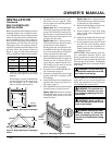
2. Fold floor anchor as shown in Figure 15.
3. Insert floor anchor (wings first) into
hole. Tap anchor flush to floor.
4. Insert mounting screws through base
and into floor anchors.
5. Tighten screws until base is firmly fas-
tened to floor.
Figure 15 - Folding Anchor
INSTALLATION
Continued
Continued
* Purchase the optional A.G.A. design-certified manual shutoff valve from your dealer. See
Accessories, page 21.
** Minimum inlet pressure for purpose of input adjustment.
Tee
Joint
Pipe
Nipple
Cap
3" Minimum
Sediment
Trap
Gas
Control
From
Gas Meter
(5" W.C.** to
10.5" W.C.
Pressure)
A.G.A. Design-Certified Manual
Shutoff Valve With 1/8" NPT Tap*
Approved Flexible
Gas Hose
Figure 16 - Gas Connection