


www.desatech.com
113897-01C
18
INSTALLATION
Continued
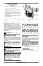
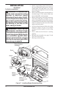
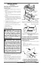
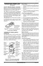
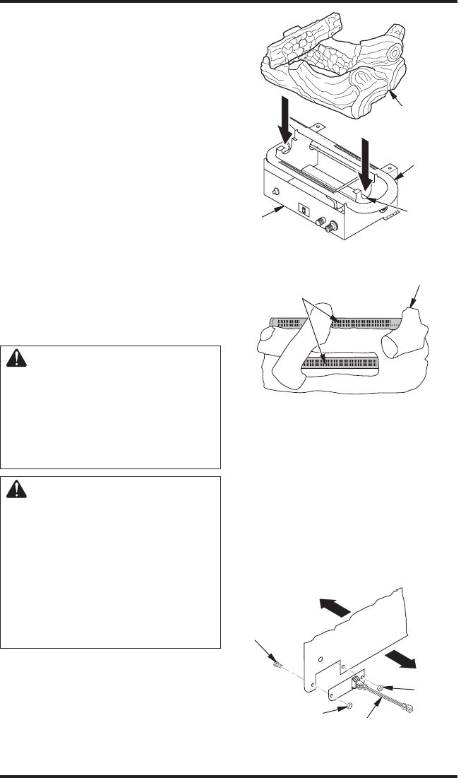
Figure 26 - Installing One-Piece Log Set
A
U
T
O
O
F
F
O
N
One Piece
Log Set
Burner
“U”-shaped
Cutout in
Chassis
Chassis
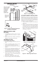
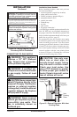
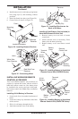
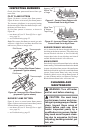
Figure 27 - Installing One-Piece Log set
(Top View)
One Piece Log Set
Burner
Ports
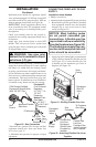
PRESSURE TESTING HEATER GAS
CONNECTIONS
1. Open equipment shutoff valve (see Figure 23,
page 17).
2. Open main gas valve located on or near gas
meter for natural gas or open propane/LP
supply tank valve.
3. Make sure control knob of heater is in the OFF
position.
4. Check all joints from equipment shutoff valve to
thermostat gas valve (see Figures 24 and 25, page
17). Apply noncorrosive leak detection fluid to all
joints. Bubbles forming show a leak.
5. Correct all leaks at once.
6. Light heater (see Operating Heater, page 20).
Check all other internal joints for leaks.
7. Turn off heater (see To Turn Off Gas to Appli
-
ance, page 21).
8. Replace front panel.
INSTALLING LOGS
WARNING: Failure to posi-
tion the parts in accordance
with these diagrams or failure
to use only parts specifically
approved with this heater may
result in property damage or
personal injury.
CAUTION: After installa-
tion and periodically thereafter,
check to ensure that no flame
comes in contact with any log.
With the heater set to HI, check
to see if flames contact any log. If
so, reposition logs according to
the log installation instructions
in this manual. Flames contact-
ing logs will create soot.
It is very important to install the logs exactly as
instructed. Do not modify logs. Only use logs
supplied with heater.
Place one-piece log set on grate to fit as illustrated
in Figure 26. Make sure back section of log set is
seated into “U”-shaped cutout in center of chassis
(see Figure 26). IMPORTANT: Make sure log does
not cover any burner ports (see Figure 27).
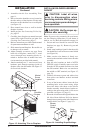
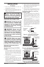
OPTIONAL WIRELESS HAND-HELD
REMOTE CONTROL ACCESSORIES
(CGHRCB & CGHRCTB Series)
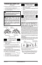
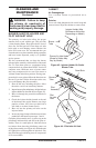
Installing Receiver
1. Disconnect switch wires from the control
valve.
2. Remove screws and nuts.
3. Remove switch plate (see Figure 28). Discard
after removing.
Front
Back
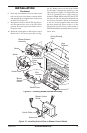
Figure 28 - Switch Plate and Wiring
Harness (Switch Plate and Orientation
May Vary Depending On Model)
Wires
Nut
Nut
Screw
Front
Back