


www.desatech.com
113897-01C
13
INSTALLATION
Continued
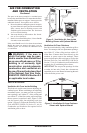
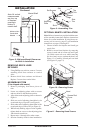
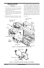
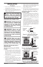
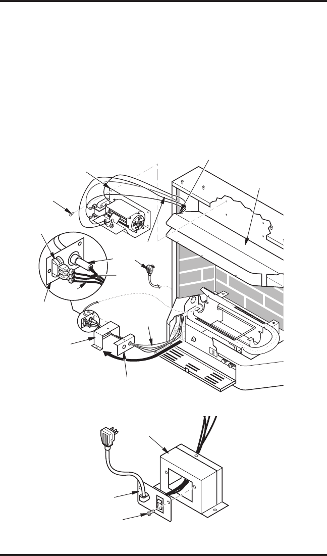
Figure 15 - Installing Blower Bracket Assembly
Wire Harness
Blower Bracket
Assembly
Screw
Power
Cord
Blower
Control
Shield
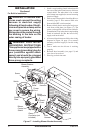
Shield Cover
Wire
Harness
Switch
Heat
Deflector
Wiring Routing
Hole
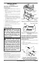
Blue
Red
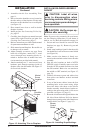
Switch Plate
Blower Control
Shield
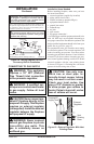
Figure 16 - Installing Switch Plate to Blower Control Shield
Switch Plate
Screw
8. Insert the 4 wire harness into one of the round
holes in the rear of the blower control shield
and through the rectangular hole in the front
of shield (see Figure 15).
9. Reconnect red wire to the AUTO switch posi
-
tion. Reconnect blue wire to the ON switch
position. Reconnect green and white wires to
the power cord.
10. Install the switch plate on the blower control
shield with 2 - #10 screws provided (see Fig
-
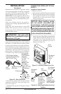
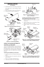
ure 16). Route power cord out of the cabinet
by inserting it through the bushing on the
outer casing (see Figure 15). Plug fan kit into
120-Volt grounded power supply and test
operation. Note: When switch is in the AUTO
position, the fan will start after the heater has
run for a few moments. The fan will continue
to run for several moments after the heater
has been turned off. When switch is in the
ON position, the fan will run until turned to
OFF. Reinstall hood assembly and close lower
louver door.