


5
55951
WARNING: Do not operate an unvented gas log set in
this fireplace with the chimney removed.
WARNING: When using a decorative appliance, the
damper must be removed or permanently locked in
the fully open position.
GAS LINE
A gas line may be installed for the purpose of installing a decorative
gas appliance available through your local distributor. Use only 1/2"
black iron pipe and appropriate fittings. When installing a gas line,
a shut-off valve designed for installation outside the firebox is
recommended.
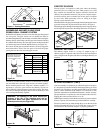
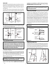
To install, remove the gas line plug located in the side firebrick
approximately 2" above the bottom, The plug must be tapped out
from the finished side towards the unfinished side (see Figure 11A).
WARNING: All gas piping and connections must be
tested for leaks after the installation is completed. Be
sure gas valve is turned on. Apply soap suds solution
to all connections and joints. If bubbles appear, leaks
must be detected and corrected. DO NOT use a match
or open flame of any kind to test leaks. Never operate
any appliance with leaky connections.
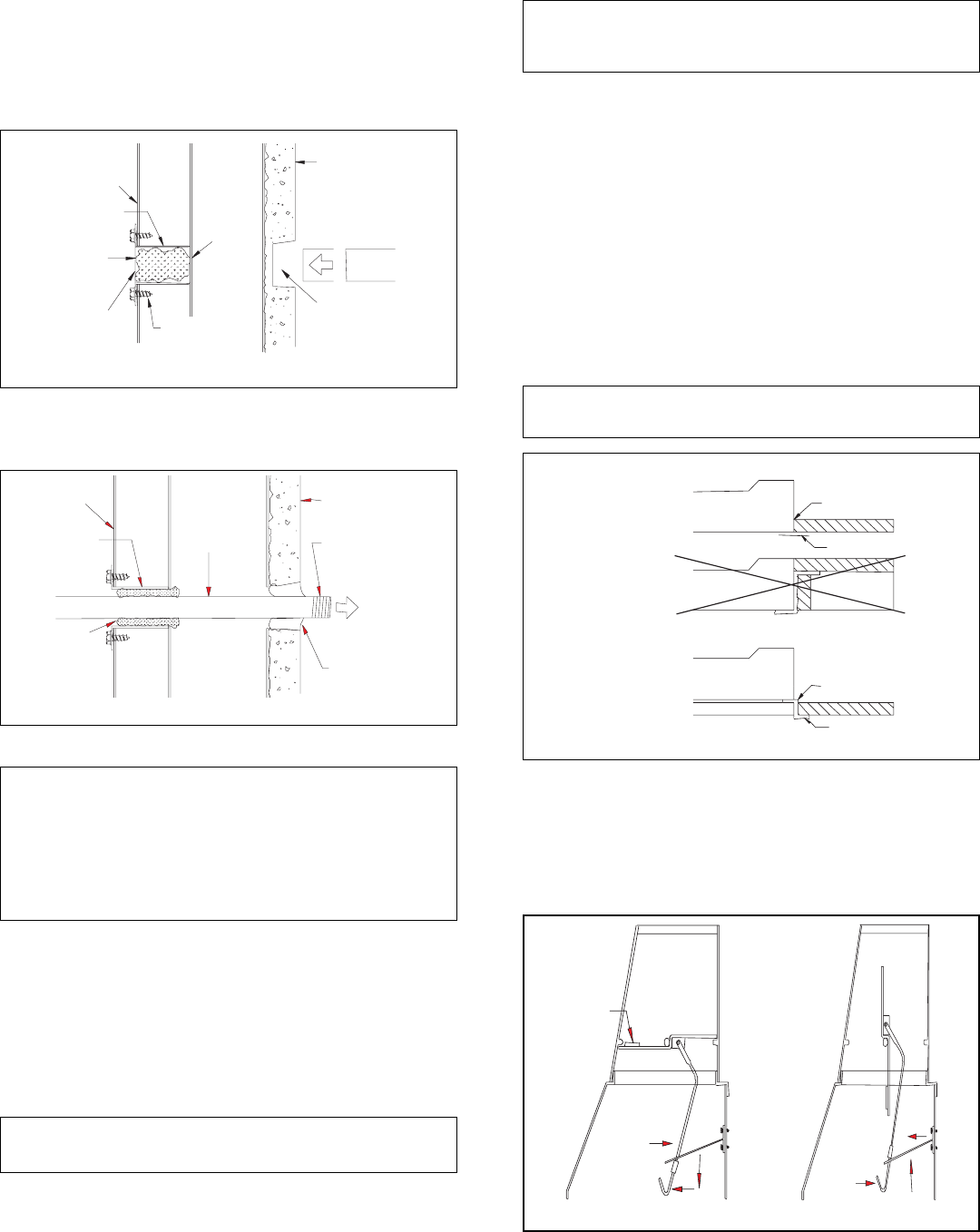
WARNING: Hearth extension is to be installed only as
illustrated.
OUTSIDE OF
FIREPLACE
GAS LINE
CONDUIT
REMOVE
KNOCKOUT
SIDE FIREBRICK
FINISHED SIDE
REFRACTORY
KNOCKOUT PLUG
REMOVE BY TAPPING
LIGHTLY WITH A
1/2" DOWEL
AFTER REMOVING
GAS LINE COVER
PLATE, REPLACE
SCREWS
REMOVE
INSULATION
TEMPORARILY
(DO NOT
DISCARD)
REMOVE
GAS CONDUIT
COVER
Figure 11A
OUTSIDE OF
FIREPLACE
GAS LINE
CONDUIT
REPACK
INSULATION
INCOMING
1/2" BLACK
IRON PIPE
PROVIDE ENOUGH
THREADED END
FOR FITTING
CONNECTION
SEAL OPENING
WITH REFRACTORY
CEMENT
SIDE FIREBRICK
FINISHED SIDE
Figure 11B
Insert the gas line parallel to the face. Fill any gap between the gas
line and the hole in the firebrick with refractory cement or commer-
cial furnace cement (see Figure 11B).
TEST FOR GAS LEAKS
The gas pipe is intended for connection to an unvented gas log set or
to a decorative gas appliance.
If you will install an unvented gas log set, ONLY VENTED GAS LOG
SETS WHICH HAVE BEEN FOUND TO COMPLY WITH THE
STANDARD FOR UNVENTED ROOM HEATERS, ANS/IAS/AGA
Z21.11.2, ARE TO BE INSTALLED IN THIS FIREPLACE.
Note:
An appropriate Comfort Glow hood must be installed when
using an unvented gas log set.
STANDARD
HEARTH
SEAL GAP
SEAL GAP
DO NOT BLOCK
INTAKE GRILL
EMBER PROTECTOR
EMBER PROTECTOR
ELEVATED
FIREPLACE
RAISED
HEARTH
NO
HEARTH
EXTENSIONS
Figure 12
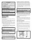
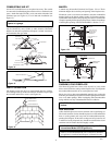
HEARTH EXTENSION
A hearth extension projecting a minimum of 20" in front of and a
minimum of 12" beyond each side of the fireplace opening is
required to protect combustible floor construction in front of the
fireplace, Use a layer of noncombustible, inorganic material having
a thermal conductivity of K=0.64 BTU IN/FT. HR. F (or less) at 1"
thick. Example of determining hearth extension equivalent. If the
material selected has a K factor of 0.25, such as glass fiber, then the
following formula would apply: 0.25/0.64 X 1" = .39" thick. This
must be covered by a noncombustible material such as tile, slate,
brick, concrete, metal, glass, marble, stone, etc. Fasten the hearth
extension to the floor to prevent shifting and seal the gap between the
fireplace frame and hearth extension with a noncombustible material
(see Figure 12).
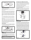
DAMPER OPERATION
The damper handle to open and close the damper blade is located inside
the firebox at the center towards the back wall. Pushing the handle back
into the keyway slot will free the damper blade to automatically open.
To close, reach in and push the handle back into the keyhole slot then pull
down and forward to lock it in place (see Figure 13).
DAMPER
WEIGHT
TO CLOSE
DAMPER
TO OPEN
DAMPER
Figure 13
If you will install a decorative gas appliance, the decorative gas
appliance must comply with the Standard for Decorative Gas
Appliances for Installation in solid Fuel burning Fireplaces,
ANS Z21.60-1996 and shall also be installed in accordance with the
National Fuel Gas code, ANS Z223.1-1996.