


3
55951
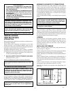
Figure 3A
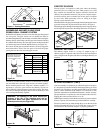
Figure 4
Figure 6
8 IN.
STAINLESS
INNER PIPE
HEMMED
END
LINEAL GAIN
PART GAIN
NO. DESCRIPTION (IN)
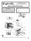
C42EC2 FIREBOX 42
C12-8DM PIPE SECTION 10
5
/
8
C18-8DM PIPE SECTION 16
5
/
8
C36-8DM PIPE SECTION 34
5
/
8
C48-8DM PIPE SECTION 46
5
/
8
CRTL-8DM ROUND
TERMINATION 6
46
5
/8"
66"
15
3
/8"
33"
12
5
/8"
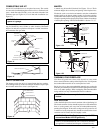
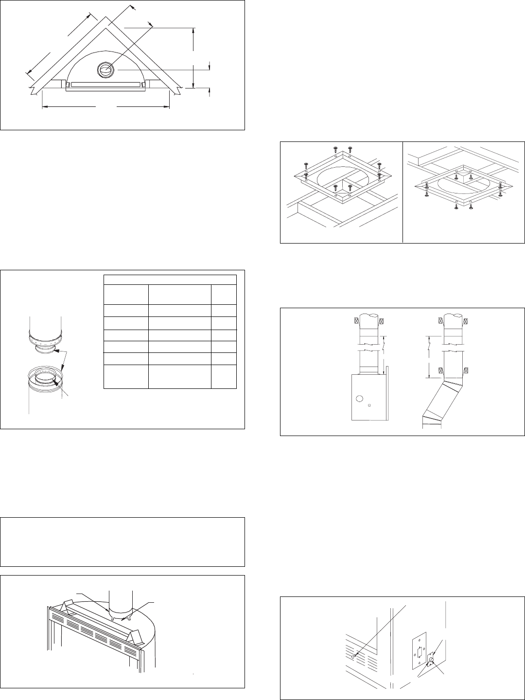
Figure 2 - Framing Dimensions
KEEP THIS
AREA OPEN
FIREPLACE
COLLAR
Figure 3B
Continue to assemble chimney sections as outlined above, making
sure that both inner and outer pipe sections are locked together.
Before installing double wall “snap lock” chimney together, it is
important to assure the joint between the chimney sections are
locked. Check by pulling chimney upward after locking. The chim-
ney will not come apart if properly locked. It is not necessary to add
screws to keep the chimney together.
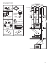
SUPPORT SECTIONS
The chimney support section is a 4 strap 12” length of pipe. A
chimney support is required at the 30 foot level above the fireplace
after a straight on the fireplace and elbows when high chimneys are
installed.
WARNING: The opening in the collar around the
chimney at the top of the fireplace must not be
obstructed. Never use blown insulation to fill the
chimney enclosure (see Figure 3B).
Figure 5
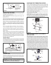
Figure 7
BLOWER
SWITCH
GROUND SCREW
ELECTRICAL
COVER PLATE
STRAIN RELIEF
30 FT.
30 FT.
RETURN
ELBOW
V12S-8DM
SUPPORT
V12S-8DM
SUPPORT
LINEAL GAIN: THE ACTUAL
MEASURABLE LENGTH OF A
PART AFTER TWO OR MORE
PARTS ARE CONNECTED.
12
3
/8 GALVANIZED OUTER
PIPE
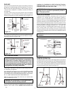
ASSEMBLING AND INSTALLING YOUR
DOUBLE-WALL CHIMNEY SYSTEM
Each double wall chimney section consists of an outer pipe, flue pipe and
one wire spacer. The pipe sections are not unitized and must be
assembled independently as the chimney is installed. When starting the
chimney directly on the firebox, the flue pipe section must be installed
first, with the lanced side up. The outer pipe section can then be installed
over the flue pipe section with the hemmed end up. (see Figure 3A).
Press down on each pipe section until the lances securely engage the
hem on the firebox starter. The wire spacer will assure the proper
spacing between the inner and outer pipe sections.
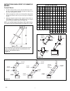
FIRESTOP SPACERS
Firestop spacers are required at each point where the chimney
penetrates a floor or ceiling joist space. Their purpose is two fold,
they establish and maintain the required clearance between the
chimney and combustible materials, and provide complete separa-
tion from one floor space to another floor or attic space as required
by most codes. When penetrating a floor or ceiling at an angle,
firestop in pack should be used.
When the double wall pipe passes through a framed opening into an attic
space, the firestop must be placed into the attic floor as in Figure 4.
When the pipe passes through a framed opening into a living space above,
the firestop must be placed on to the ceiling from below as in Figure 5.
BLOWER ASSEMBLY (CBK3)
A blower assembly is available for use with this fireplace as an option.
It is designed to be installed on DESA International factory pre-wired
fireplaces only. The blower assembly model CBK3 can be installed
prior to or after installation of the fireplace. Use of blowers or fans
other than manufactured by DESA International voids the warranty.
The optional blower is operated by a switch located on the lower face.
Flipping the switch turns the blowers on or off.
Note:
Fireplace must be wired to the house electrical system in order for
blowers to operate. See instructions provided with blower assembly.
Electrical connections are made through the cover on the side of the
fireplace illustrated in Figure 7. Use 14 AWG min. copper wire for
all connections. Be certain the fireplace is properly grounded.
C12S-8DM
SUPPORT
C12S-8DM
SUPPORT