


4
55951
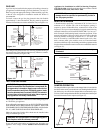
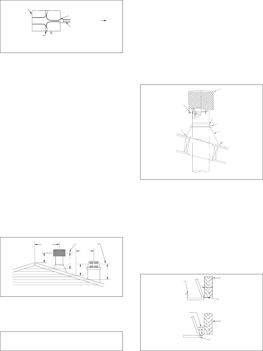
Figure 8
10 FOOT RULE
2' MIN.
2' MIN.
LEVEL OF FLUE
GAS OUTLET
10'
3' MIN.
3' MIN.
10'
OR LESS
ATTACH BRACKET
TABS TO OUTER
PIPE (3 PLACES)
SECURE WITH
SCREWS
OVERLAP
SHINGLES
TOP AND SIDES
CRTL-8DM
FLUE PIPE OF CRTL-8DM
INSIDE INNER PIPE OF
CHIMNEY
CAULK
COLLAR
FLASHING
UNDERLAP SHINGLES
BOTTOM ONLY
Figure 9
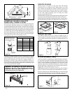
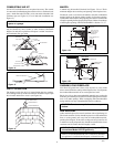
PENETRATING THE ROOF
To maintain a 2-inch clearance to the pipe on a roof with a pitch, a
rectangular opening must be cut.
STEP 1: Determine the center point through which the pipe will
penetrate the roof.
STEP 2: Determine the pitch of the roof. Pitch is the distance the roof
drops over a given span, usually 12 inches. A 6/12 pitch means that
the roof drops 6 inches for each 12 inches measured horizontally.
STEP 3: From the center point determined in STEP 1, measure an
opening 17
1
/4 inches wide (8
5
/8 inches to each side of the center
point). For a roof pitch between 0/12 (flat) and 6/12, measure an
opening 21 inches long (10
1
/2 inches above and below the center
point).
6/12 to 12/12 pitches: Measure 26 inches (13 above and below).
12/12 to 18/12 pitches: Measure 32
1
/2 inches (16
1
/4 above and below).
18/12 to 24/12 pitches: Measure 40 inches (20 above and below).
STEP 4: Remove the roofing around the opening measured and cut
out this section.
STEP 5: Add the next sections of pipe until the end penetrates the
roof line. Check to see that proper clearances are maintained. Extend
chimney by adding sections of double wall pipe until pipe is a
minimum of 30 inches above highest point of roof cutout. Termina-
tion and chimney must extend a minimum of 36 inches above highest
point where it passes through roof.
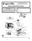
10 FOOT RULE
All chimney terminations must extend a minimum of 3 feet in height
above the highest point where it passes through the roof and must be
at least 2 feet above the peak of the roof if within a horizontal distance
of 10 feet from the peak (see Figure 8).
TERMINATIONS
The fireplace and chimney system must be vented to the out-of-doors
and must be terminated with the listed round top or chase termina-
tions. If a chase termination is desired, refer to the instructions
supplied with the termination.
WARNING: Do not seal ventilation openings on the
rooftop flashing. Follow the installation instructions
provided with the termination being used.
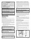
FOR ROUND TOP TERMINATION ON ROOF
STEP 1: Slide the flashing over the pipe (no firestop is needed at the
roof level). Tack the flashing down at the top two corners with
roofing nails. Lay roofing over the top and sides of the flashing and
secure them to the roof through the flashing with roof nails. Place
roofing under the lower edge and secure to the roof.
Cover all nail heads with mastic or roof cement.
STEP 2: Install the storm collar on double wall chimney, push collar
down to flashing and seal (see Figure 9).
STEP 3: Place the CRTL-8DM on to the pipe end as illustrated and
secure with the screws provided.
IMPORTANT:
If an exposed portion of chimney is greater than 5
feet above the roof line, use support wires to keep chimney secure.
The support wires may be attached to the outer pipe of the chimney
with screws, provided the screws are no longer than 3/4".
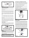
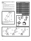
FIREPLACE ENCLOSURE: COLD CLIMATE
INSTALLATIONS
Before finishing the enclosure around the fireplace, inspect all joints
around the fireplace. Any gaps between the nailing flanges and the
framing should be sealed with noncombustible insulation or caulking (see
Figure 10). Inspect the fireplace joints for possible gaps caused by
shipping or mishandling during installation. These should be sealed with
noncombustible materials. If the fireplace is mounted on a raised platform
insulate below the platform to prevent the entry of cold air through the
fireplace bottom by means of conduction. The above steps are import
especially if the fireplace is installed in cold weather climate. The opening
around the base of the chimney must remain open and free to circulate
outside air for keeping the chimney cool as designed (see Figure 3B, page
3). The fireplace must be set on a continuous platform to prevent cold air
from conducting through the metal bottom. The platform bottom may be
constructed of any wood product or other materials such as cement.
FIREPLACE
SIDE FRAME
FIREPLACE
SIDE FRAME
NORMAL FRAMING
PACK
INSULATION
HERE
WIDE FRAMING
SIDE
FRAMING
SIDE
FRAMING
3/4 CLEARANCE
NOT REQUIRED
AT THE FRAMING
CAULK HERE
Figure 10
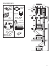
10', 14 GA. W/GROUND
ROMEX ADDED TO U.L.
LISTED (MM11306)
FIREPLACE AT THE
FACTORY
COVER PLATE WITH
STRAIN RELIEF
TO WALL SWITCH
EXISTING “J” BOX
IN FIREPLACE
WIRE NUT (TYP.)
Figure 8