


www.desatech.com
114909-01A
8
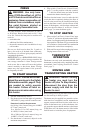
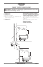
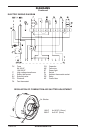
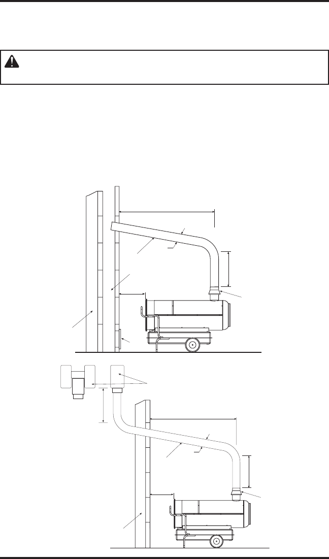
EXHAUST PIPE POSITIONING DIAGRAM
DIAGRAMS
Continued
5
4
A
3
2
D
C
1
B
A
6
2
D
C
1
B
5
E
WARNING: The diagrams are typical; the installation of the flue
must meet current legal norms.
1. Anti-wind device fitted with the heater
2. Horizontal crosspiece with a minimum
upwards angle of at least 5°, minimum 1"
up for every 12" of horizontal travel
3. Flue with minimum internal dimensions
of 8" x 8"
4. Anti-explosion/flue inspection shutter
5. External buffer wall
6. H-shape draw activator
A. Minimum 3 ft.
B. Minimum 3 ft.
C. As short as possible
D. Equal to or greater than the diameter of
the burner’s flue output
E. Minimum 3 ft.