


www.desatech.com
7114909-01A
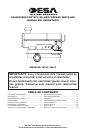
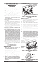
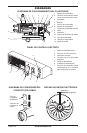
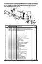
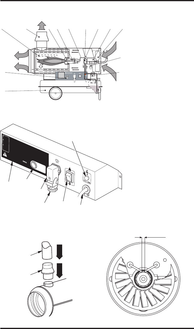
DIAGRAMA DE FUNCIONAMIENTO DEL CALENTADOR
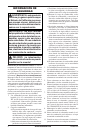
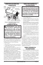
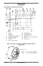
PANEL DE CONTROL ELÉCTRICO
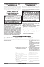
DISTANCIAS ENTRE ELECTRODOS
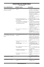
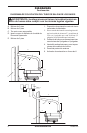
DIAGRAMA DE CONEXIONES DEL
CONDUCTO DE HUMOS
DIAGRAMAS
1. Cámara de combustión
2. Conexión de protección contra
viento del conducto de humos
3. Quemador
4. Boquilla
5. Circuito de combustible
6. Bomba de combustible
7.
Válvula de combustible eléctrica
8. Motor
9. Ventilador
10.
Soporte de devanado de cables
11. Filtro de combustible
12. Tanque de combustible
13. Panel de control
1 2 3 6 8 9
12
13
11
4
5 7
10
0.08" - 0.12"
(2-3 mm)
!
C
A
UT
IO
N
:
H
o
t
w
h
i
le
i
n
o
pe
rati
o
n
.
D
o
n
o
t
to
u
c
h.
Ke
e
p
c
h
il
d
ren,
a
n
im
a
ls
,
c
lo
th
in
g
a
n
d
c
o
m
b
us
t
i
bl
e
s
aw
a
y.
!
P
R
E
CA
UC
I
Ó
N:
C
al
ie
n
te
cu
a
nd
o
e
s
t
á
en
o
p
e
r
ac
ió
n
.
No
t
ocar
.
M
a
n
te
n
g
a
a lo
s
n
iñ
o
s
,
a
ni
m
a
l
e
s
,
v
e
s
t
im
e
nt
a
y
c
om
b
u
s
ti
b
l
es
a
le
-
j
ad
o
s.
!
AT
T
E
N
T
IO
N
:
L’
ap
pa
re
i
l
de
c
hauffage
e
s
t
b
rû
la
n
t
p
en
d
a
n
t
l
e
fo
n
c
t
i
o
n
ne
m
e
nt.
N
e
le
to
u
c
he
z
p
a
s
.
T
e
n
e
z
l
es
e
n
fa
n
ts
, les
a
nim
a
u
x
e
t
l
es
vê
t
e
m
e
n
t
s
à
l’
é
c
ar
t
d
e
c
e
t
ap
p
a
re
il
.
O
P
E
R
A
T
IN
G
I
N
S
T
R
U
C
T
IO
N
S
ST
A
RT
1
.
Fill
t
a
nk
-
U
se
o
nl
y
ke
ro
se
n
e
,
#
1
&
#
2
d
ie
se
l
a
n
d
f
u
el
o
il
,
JE
T
A
o
r
JP
-
8
f
ue
l
s.
2
.
P
lu
g
p
ow
e
r
cord
i
n
to
12
0V
/6
0
Hz
outl
et
.
Po
w
e
r
in
d
icator
lig
h
t
sh
o
ul
d
be
on
.
3
.
If
e
q
u
ip
pe
d
, ad
j
us
t th
e
r
m
o
s
ta
t
k
no
b
to
t
he wa
rm
es
t
sett
i
ng
.
4
.
P
u
s
h
ON
/
OF
F
sw
itch
t
o
O
N
()
.
F
a
n
m
o
to
r
sh
ou
ld
s
t
ar
t
i
mm
e
d
ia
t
e
ly
.
He
a
te
r
wi
l
l
i
gn
i
te
wi
th
i
n
1
0
s
econds
.
5
.
If
eq
ui
p
pe
d,
ad
j
u
s
t
th
e
rm
osta
t to desired
s
etti
n
g
.
ST
OP
Pu
s
h
O
N
/
O
F
F
sw
it
c
h
to
OF
F
(
O).
F
a
n
m
o
to
r
wi
l
l
cont
i
n
u
e
to
r
u
n.
Do
n
o
t
un
plug he
a
te
r
u
n
t
i
l
c
o
o
l
in
g
c
y
cl
e
i
s
c
o
mp
l
e
te.
S
e
e
m
o
d
e
l
d
e
c
a
l
o
r
o
w
n
er
’s
m
a
n
u
a
l
f
or
a
d
d
i
t
io
n
a
l
o
p
e
r
a
t
i
n
g
i
n
s
t
r
u
c
-
t
io
n
s
,
s
a
fe
t
y
r
e
q
u
i
r
e
m
e
n
t
s
,
a
n
d
s
p
e
c
i
fi
c
a
t
i
o
n
s
.
O
PE
R
A
T
I
N
G
I
N
S
T
R
U
C
T
I
O
N
S
ST
A
R
T
1
.
Fill
t
a
n
k
-
U
se
o
nl
y
ker
os
e
n
e
,
#
1
&
#
2
d
ie
s
el
a
n
d
f
u
e
l
o
i
l
,
JE
T
A
o
r
JP
-
8
f
u
e
l
s.
2
.
P
lu
g
p
o
we
r
co
r
d
in
t
o
1
2
0V
/
6
0
H
z
o
u
t
le
t.
P
ow
er
i
n
d
icator
ligh
t
should
be
on
.
3
.
If
e
q
u
ip
pe
d
, adju
s
t
t
he
r
m
os
ta
t kn
o
b
to
t
he
warmes
t
se
t
t
i
n
g
.
4
.
P
u
sh
ON
/OFF
sw
it
ch
t
o
ON
(
)
. Fa
n
mo
t
or
s
h
o
u
ld
st
a
r
t
i
mm
e
di
-
a
tely
. He
a
te
r
wi
l
l
i
gn
i
te
wi
th
i
n
1
0
se
co
n
ds
.
5
.
If
eq
ui
p
pe
d, ad
j
us
t
ther
m
o
st
at
to desir
e
d sett
i
ng
.
ST
OP
Pu
s
h
O
N
/
O
F
F
s
w
i
t
c
h
to OF
F
(
O
)
.
F
an
mo
t
or
wi
l
l
co
n
ti
n
u
e
to
r
u
n.
Do
n
o
t
u
n
plug
h
e
a
te
r
u
nt
i
l co
o
l
in
g
c
y
cl
e
i
s
c
om
p
l
e
te
.
Se
e
mo
d
el
d
e
c
a
l
or
o
w
n
er
’
s
m
a
n
u
a
l
f
or
a
d
d
it
i
o
n
a
l
o
p
er
at
i
n
g
in
st
r
u
c
-
t
io
n
s
,
s
a
fe
t
y
r
e
q
u
i
r
e
m
e
n
t
s
,
an
d
s
p
e
c
i
fi
c
a
t
i
o
n
s
.
O
PE
R
A
T
I
N
G
IN
S
TR
U
C
T
IO
NS
ST
A
RT
1.
Fi
l
l
t
a
n
k
-
Us
e
o
nl
y
ke
r
ose
ne
,
#
1
&
#
2
d
iese
l
a
n
d
f
u
el
o
il
,
JET
A
o
r
JP-8
f
u
e
ls
.
2.
P
lu
g
p
ow
e
r
co
rd
in
t
o
1
2
0
V
/
6
0
Hz
o
u
t
le
t
.
Po
w
e
r
i
n
d
i
ca
to
r
li
gh
t
s
h
ou
l
d
be
o
n.
3.
If
eq
ui
p
pe
d
,
a
d
ju
s
t
the
rm
os
t
at
k
n
ob
to the
wa
r
m
es
t
sett
i
ng
.
4
.
P
us
h
ON
/
OF
F
sw
it
ch
t
o
ON ()
.
F
an
mo
t
or
should
st
a
r
t
i
mm
e
d
i
-
ate
l
y
. He
at
e
r
wi
l
l
i
g
n
i
te
wi
t
hi
n
1
0
s
econ
d
s
.
5
.
I
f
e
q
u
i
p
pe
d,
ad
j
us
t
t
he
r
m
os
tat
t
o
d
esired
s
e
tt
i
n
g
.
S
T
OP
Pu
s
h
ON/O
F
F
swit
c
h
to
OFF
(
O
).
F
a
n
moto
r
wi
l
l
c
o
n
t
in
u
e
t
o
r
u
n.
Do
no
t
u
np
l
u
g
he
at
e
r
un
ti
l
c
o
ol
i
n
g
cy
c
le
is
c
o
mp
l
e
t
e
.
S
e
e
m
o
d
e
l
d
e
c
a
l
or
o
w
ne
r
’
s
m
a
n
u
a
l
f
or
a
d
d
it
io
n
a
l
o
pe
r
a
t
i
ng
i
n
s
t
r
u
c
-
t
i
o
n
s
,
s
a
fe
ty
r
e
qu
i
r
e
m
e
n
t
s,
a
n
d
s
pe
c
i
fic
a
t
i
o
n
s
.
2
7
0
0
1
I
n
d
us
t
ri
a
l
D
ri
v
e
P.
O
.
B
o
x
9
00
4
Bo
wl
i
n
g
G
r
e
en
,
K
y
4
2
1
0
2
w
ww
.
d
e
s
at
e
c
h
.
co
m
1
13
3
44
-0
8
U
N
PL
U
G
HE
A
T
E
R
B
E
F
O
R
E
R
E
M
O
V
I
NG
CO
VE
R
U
N
P
LU
G
HE
A
T
E
R
B
E
F
O
RE
R
E
M
O
V
I
N
G
CO
V
ER
U
N
P
L
U
G
HE
A
T
E
R
B
E
F
O
R
E
RE
M
OV
I
N
G
C
OV
E
R
Ma
de
i
n
I
t
a
l
y
FLA
M
E
C
O
N
TRO
L
R
E
S
E
T
F
LA
M
E
CO
N
TR
O
L
R
E
S
E
T
FLA
M
E
C
O
N
T
RO
L
R
E
S
E
T
M
a
n
uf
ac
t
u
re
d
f
o
r
:
1. Botón de restablecimiento
2. Etiqueta de funcionamiento
3. Interruptor principal
4. Conector para el termostato
ambiental
5. Cable de alimentación
6. Indicador de alimentación
7. Enchufe del termostato (debe
mantenerse fijo si no se utiliza
algún dispositivo de control)
2
1
3
4
7
5
6
Tubo de
6 pulgadas
de diámetro
Conector del
conducto de
humos
2-3 mm
(0,08 - 0.12 pulgadas)