


www.desatech.com
7114909-01A
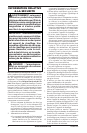
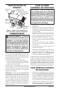
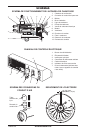
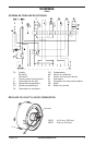
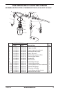
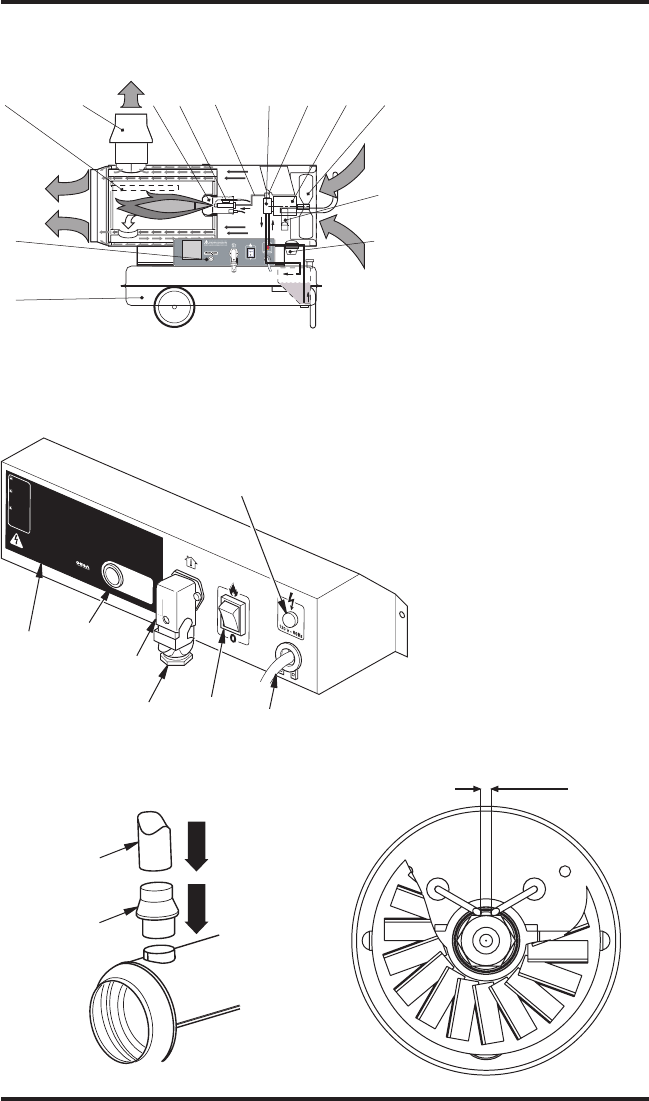
PANNEAU DE CONTRÔLE ÉLECTRIQUE
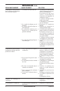
ESPACEMENT DE L’ÉLECTRODE
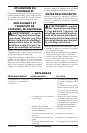
SCHÉMA DES CONNEXIONS DU
CONDUIT D’AIR
SCHÉMAS
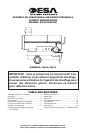
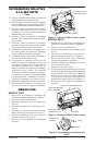
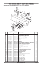
SCHÉMA DE FONCTIONNEMENT DE L’APPAREIL DE CHAUFFAGE
1. Chambre de combustion
2.
Connexion du conduit d’air pare-vent
3. Brûleur
4. Buse d’aération
5. Ligne de carburant
6. Pompe de carburant
7. Vanne de carburant électrique
8. Moteur
9. Ventilateur
10. Enrouleur de cordon
11. Filtre à carburant
12. Réservoir de carburant
13. Panneau de contrôle
1 2 3 6 8 9
12
13
11
4
5 7
10
0.08" - 0.12"
(2-3 mm)
!
C
A
UT
IO
N
:
H
o
t
w
h
i
le
i
n
o
pe
rati
o
n
.
D
o
n
o
t
to
u
c
h.
Ke
e
p
c
h
il
d
ren,
a
n
im
a
ls
,
c
lo
th
in
g
a
n
d
c
o
m
b
us
t
i
bl
e
s
aw
a
y.
!
P
R
E
CA
UC
I
Ó
N:
C
al
ie
n
te
cu
a
nd
o
e
s
t
á
en
o
p
e
r
ac
ió
n
.
No
t
ocar
.
M
a
n
te
n
g
a
a lo
s
n
iñ
o
s
,
a
ni
m
a
l
e
s
,
v
e
s
t
im
e
nt
a
y
c
om
b
u
s
ti
b
l
es
a
le
-
j
ad
o
s.
!
AT
T
E
N
T
IO
N
:
L’
ap
pa
re
i
l
de
c
hauffage
e
s
t
b
rû
la
n
t
p
en
d
a
n
t
l
e
fo
n
c
t
i
o
n
ne
m
e
nt.
N
e
le
to
u
c
he
z
p
a
s
.
T
e
n
e
z
l
es
e
n
fa
n
ts
,
les
a
nim
a
u
x
e
t
l
es
vê
t
e
m
e
n
t
s
à
l’
é
c
ar
t
d
e
c
e
t
ap
p
a
re
il
.
O
P
E
R
A
T
IN
G
I
N
S
T
R
U
C
T
IO
N
S
ST
A
RT
1
.
Fill
t
a
nk
-
U
se
o
nl
y
ke
ro
se
n
e
,
#
1
&
#
2
d
ie
se
l
a
n
d
f
u
el
o
il
,
JE
T
A
o
r
JP
-
8
f
ue
l
s.
2
.
P
lu
g
p
ow
e
r
cord
i
n
to
12
0V
/6
0
Hz
outl
et
.
Po
w
e
r
in
d
icator
lig
h
t
sh
o
ul
d
be
on
.
3
.
If
e
q
u
ip
pe
d
, ad
j
us
t th
e
r
m
o
s
ta
t
k
no
b
to
t
he wa
rm
es
t
sett
i
ng
.
4
.
P
u
s
h
ON
/
OF
F
sw
itch
t
o
O
N
()
.
F
a
n
m
o
to
r
sh
ou
ld
s
t
ar
t
i
mm
e
d
ia
t
e
ly
.
He
a
ter
wi
l
l
i
gn
i
te
wi
th
i
n
1
0
s
econ
ds
.
5
.
If
eq
ui
p
pe
d,
ad
j
u
s
t
th
e
rm
osta
t to desired
s
etti
n
g
.
ST
OP
Pu
s
h
O
N
/
O
F
F
sw
it
c
h
to
OFF
(
O).
F
a
n
m
o
to
r
wi
l
l
cont
i
n
u
e
to
r
u
n.
Do
n
o
t
un
plug he
a
te
r
u
n
t
i
l
c
o
o
l
in
g
c
y
cl
e
i
s
c
o
mp
l
e
te.
S
e
e
m
o
d
e
l
d
e
c
a
l
o
r
o
w
n
er
’s
m
a
n
u
a
l
f
or
a
d
d
i
t
io
n
a
l
o
p
e
r
a
t
i
n
g
i
n
s
t
r
u
c
-
t
io
n
s
,
s
a
fe
t
y
r
e
q
u
i
r
e
m
e
n
t
s
,
a
n
d
s
p
e
c
i
fi
c
a
t
i
o
n
s
.
O
PE
R
A
T
I
N
G
I
N
S
T
R
U
C
T
I
O
N
S
ST
A
R
T
1
.
Fill
t
a
n
k
-
U
se
o
nl
y
ker
os
e
n
e
,
#
1
&
#
2
d
ie
s
el
a
n
d
f
u
e
l
o
i
l
,
JE
T
A
o
r
JP
-
8
f
u
e
l
s.
2
.
P
lu
g
p
o
we
r
co
r
d
in
t
o
1
2
0V
/
6
0
H
z
o
u
t
le
t.
P
ow
er
i
n
d
icator
ligh
t
should
be
on
.
3
.
If
e
q
u
ip
pe
d
, adju
s
t
t
he
r
m
os
ta
t kn
o
b
to
t
he
warmes
t
se
t
t
i
n
g
.
4
.
P
u
sh
ON
/OFF
sw
it
ch
t
o
ON
(
)
. Fa
n
mo
t
or
s
h
o
u
ld
st
a
r
t
i
mm
e
di
-
a
tely
. He
a
te
r
wi
l
l
i
gn
i
te
wi
th
i
n
1
0
se
co
n
ds
.
5
.
If
eq
ui
p
pe
d, ad
j
us
t
ther
m
o
st
at
to desir
e
d sett
i
ng
.
ST
OP
Pu
s
h
O
N
/
O
F
F
s
w
i
t
c
h
to OF
F
(
O
)
.
F
an
mo
t
or
wi
l
l
co
n
ti
n
u
e
to
r
u
n.
Do
n
o
t
u
n
plug
h
e
a
te
r
u
nt
i
l co
o
l
in
g
c
y
cl
e
i
s
c
om
p
l
e
te
.
Se
e
mo
d
el
d
e
c
a
l
or
o
w
n
er
’
s
m
a
n
u
a
l
f
or
a
d
d
it
i
o
n
a
l
o
p
er
at
i
n
g
in
st
r
u
c
-
t
io
n
s
,
s
a
fe
t
y
r
e
q
u
i
r
e
m
e
n
t
s
,
an
d
s
p
e
c
i
fi
c
a
t
i
o
n
s
.
O
PE
R
A
T
I
N
G
IN
S
TR
U
C
T
IO
NS
ST
A
RT
1.
Fi
l
l
t
a
n
k
-
Us
e
o
nl
y
ke
r
ose
ne
,
#
1
&
#
2
d
iese
l
a
n
d
f
u
el
o
il
,
JET
A
o
r
JP-8
f
u
e
ls
.
2.
P
lu
g
p
ow
e
r
co
rd
in
t
o
1
2
0
V
/
6
0
Hz
o
u
t
le
t
.
Po
w
e
r
i
n
d
i
ca
to
r
li
gh
t
s
h
ou
l
d
be
o
n.
3.
If
eq
ui
p
pe
d
,
a
d
ju
s
t
the
rm
os
t
at
k
n
ob
to the
wa
r
m
es
t
sett
i
ng
.
4
.
P
us
h
ON
/
OF
F
sw
it
ch
t
o
ON ()
.
F
an
mo
t
or
should
st
a
r
t
i
mm
e
d
i
-
ate
l
y
. He
at
e
r
wi
l
l
i
g
n
i
te
wi
t
hi
n
1
0
s
econ
d
s
.
5
.
I
f
e
q
u
i
p
pe
d,
ad
j
us
t
t
he
r
m
os
tat
t
o
d
esired
s
e
tt
i
n
g
.
S
T
OP
Pu
s
h
ON
/O
F
F
swit
c
h
to
OFF
(
O
).
F
a
n
moto
r
wi
l
l
c
o
n
t
in
u
e
t
o
r
u
n.
Do
no
t
u
np
l
u
g
he
at
e
r
un
ti
l
c
o
ol
i
n
g
cy
c
le
is
c
o
mp
l
e
t
e
.
S
e
e
m
o
d
e
l
d
e
c
a
l
or
o
w
ne
r
’
s
m
a
n
u
a
l
f
or
a
d
d
it
io
n
a
l
o
pe
r
a
t
i
ng
i
n
s
t
r
u
c
-
t
i
o
n
s
,
s
a
fe
ty
r
e
qu
i
r
e
m
e
n
t
s,
a
n
d
s
pe
c
i
fic
a
t
i
o
n
s
.
2
7
0
0
1
I
n
d
us
t
ri
a
l
D
ri
v
e
P.
O
.
B
o
x
9
00
4
Bo
wl
i
n
g
G
r
e
en
,
K
y
4
2
1
0
2
w
ww
.
d
e
s
at
e
c
h
.
co
m
1
13
3
44
-0
8
U
N
PL
U
G
HE
A
T
E
R
B
E
F
O
R
E
R
E
M
O
V
I
NG
CO
VE
R
U
N
P
LU
G
HE
A
T
E
R
B
E
F
O
RE
R
E
M
O
V
I
N
G
CO
V
ER
U
N
P
L
U
G
HE
A
T
E
R
B
E
F
O
R
E
RE
M
OV
I
N
G
C
OV
E
R
Ma
de
i
n
I
t
a
l
y
FLA
M
E
C
O
N
TRO
L
R
E
S
E
T
F
LA
M
E
CO
N
TR
O
L
R
E
S
E
T
FLA
M
E
C
O
N
T
RO
L
R
E
S
E
T
M
a
n
uf
ac
t
u
re
d
f
o
r
:
1. Bouton de réinitialisation
2. Étiquette d'utilisation
3. Interrupteur principal
4.
Connecteur du thermostat ambiant
5. Cordon électrique
6. Indicateur de mise sous tension
7. Prise du thermostat (doit être sécu
-
risée si aucun appareil de contrôle
n’est utilisé)
2
1
3
4
7
5
6
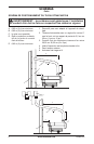
Tube -
diamètre de
6 po
Raccord du
conduit d’air
de 2 à 3mm
(de 0,08 à 0,12 po)