


2
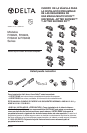
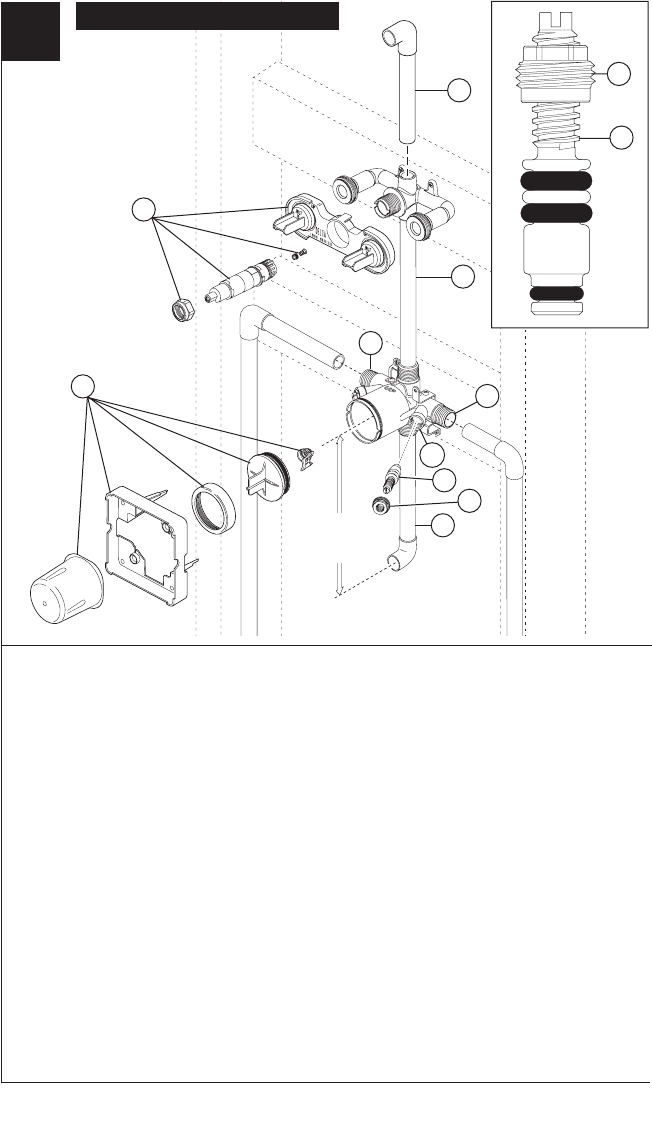
R18448 & R18448-WS Installation
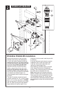
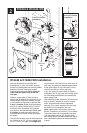
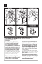
Remove the bonnet nut, stem and stem
extender, seat, spring, and plasterguard
(1), plus, the screen, test cap, bonnet nut,
plasterguard and cover (2) before soldering.
Connect valve body to water supplies using
the prop
er fittings. Note: (3) is the cold
inlet port and (4) is the hot inlet port.
Solder a copper tube (5) from the valve
body to the jet module so the jets are at
the desired height. Solder another tube (6)
onto the top of the jet module to the shower
arm elbow to the desired height. It is
recommended to mount valves to stringers
as shown.
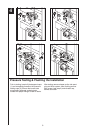
The pipe (7) between valve & tub spout
must be a minimum of 1/2" (13 mm) copper
pipe or 1/2" (13 mm) iron pipe in a straight
drop no less than 8" (203 mm) but no more
than 16" (406 mm) long with only one 90
degree elbow to the spout nipple. If any
outlet port is to be unused, seal the port with
a pipe plug.
If you are making a back to back or reverse
installation (hot on right and cold on left)
install the valve body as described, but
reverse the water supply lines.
After soldering, reinstall all parts in reverse
order; ensure bonnet nuts are tightened
securely. Then install the stops into the body;
be careful not to overtighten the nuts.
Note: Install stops in the w/stops version as
follows: Thread nut (8) on stem (9) as shown.
Then press stem and nut assembly into body
(10) and tighten using a 3/8", 6 point, deep
well socket. With a flat head screwdriver, adjust
stem clockwise to close and counterclockwise
to open.
R18448 & R18448-WS
2
1
4
3
16"
(406 mm)
Max
5
6
7
8
9
10
8
9
4