


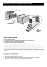
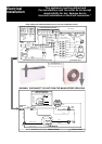

ELECTRICAL CONNECTIONS
• A 16A mains cable is connected to the indoor
unit.
• If this cable is too short, a qualified electrician
should replace it.
• An interconnecting cable complying with local
wiring codes, should be connected between the
indoor and outdoor units.
1. Connect the brown wire to terminal 1
2. Connect the blue wire to terminal 2
3. Connect the earth wire to the terminal marked
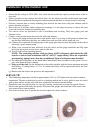
INSTALLATION OF THE INDOOR UNIT.
• Select the most suitable position for uniform air
distribution, and one that requires the shortest in-
terconnecting tubing and condensate drain pipe.
When the required interconnecting piping is longer
than 9m. an additional 20g/m of refrigerant should
be added. The maximum recommended pipe length
is 16 m. For longer lengths please refer to the pipe
sizing manuals.
• The unit must be installed at least 100mm above
floor level. Ensure that the return air outlet under-
neath the unit is not obstructed.
• The unit is supplied with 2 loose and two fixed
brackets for wall mounting. The brackets at the
rear may be removed and there are mounting holes
behind the fan assembly or optional mounting feet
are available for free standing installations, if wall
mounting is not a suitable option.
• Two openings are provided for the refrigerant piping and condensate drain tube. Both openings are on
the right hand side of the unit and cater for rear or bottom entry.
• The copper tube connections are situated behind the fan deck assembly. To remove the assembly please
proceed as follows:-
(a) Disconnect the unit from the electrical power supply.
(b) Remove the filter and the front access panel by removing the two screws at the bottom of the panel.
(c) Pull the 4 pin connector plug apart without unscrewing the electrical connections. Remove the four
screws securing the fan assembly and pull the assembly out carefully.
(d) The liquid and suction lines will now be visible. The copper tubes should be fitted with flare nuts
and stoppers.
(e) Measure and prepare the interconnecting piping prior to removing the stoppers. Ensure that the in-
terconnecting pipes are fully insulated. After connecting, insulate the fittings with non drip tape to
prevent sweating. NOTE: The unit has been pumped down after testing and only a small hold-
ing charge of R22 refrigerant will be in the indoor unit. Please take precautions when remov-
ing the stoppers.
(f)
Connect a 19mm (internal diameter) drain pipe to the drain connection. Insulate the drain pipe
where sweating could cause damage. Ensure the drain pipe is slanted to allow easy flow. Do not use
traps for the condensate drain.
(g)
For service and warranty purposes a duplicate serial sticker is located on the control panel door.
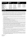
NOTE.
• An electrical isolator must be installed close to
the condensing unit.
• Ensure that the supply voltage is 230V 50 Hz.
• The unit must be earthed.
• Field wiring and connections must comply with
local codes.
• Only connect one unit to a circuit and use only
the recommended circuit breaker size.
• The evaporator and condenser must be con-
nected through the same circuit breaker.
• Please consult a qualified electrician.
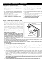
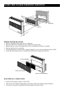
Split Console installation instructions
FIXED BRACKETS
WALL MOUNTED BRACKETS
MOUNTING HOLE
SLIDING PLATE
FIXING SCREW
MESH
DIRECTION OF MOVEMENT